
System Description

SystemDescriptionandInstallationManualforRangeFinder ICD10000‐01
©SagetechCorporation2018ConfidentialProprietaryExportControlled Page18of130
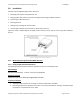
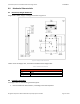
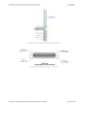
Two Transponder/ADS‐B L‐Band SMA antenna connectors.Only the bottom antenna connector is
usedby Range Finder. See the Bottom Antenna connectorin Figure6‐2,located on lower rightside
whenfacingmainconnector.
One Pressure Altitude Sensor/Encoder port to static pressure, connected to tubing with
a clamped
diameterof0.18”.
Thelocationsoftheseconnectors/portsareshowninFigure6‐2.
Figure6‐2MechanicalConnections
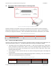
6.2.1 RangeFinderMainConnector
TheRangeFinderMainConnectorisa51‐pinMicro‐Dtypefemaleconnectorthatprovidestheinterfacetothe
hostcomputer’scommandandcontrolserialandEthernetbuses.Theconnectoralsoprovidesaninterfaceto
themainpowersource.
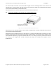
Figure6‐3shows the RangeFinder’s MainConnector (Omnetics P/N:
A99601‐512)withpinlocations.Figure
6‐4presentsanimageofthefemaleMicro D‐SubMainConnector’sfrontview,withpinnumberorienta tion .
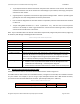
Table7‐1showsthemainconnector51‐pinassignments.
ConnectingtheMXRMainConnectortothehostrequiresashieldedcablebuiltaccordingto
standardA‐A
59569A.