
System Description

SystemDescriptionandInstallationManualforRangeFinder ICD10000‐01
©SagetechCorporation2018ConfidentialProprietaryExportControlled Page14of130
5.3 ConnecttoGPSInterface
GPSdatashouldbeprovidedtotheRangeFinder fromtheaircraftsystemintegratorinoneoftwoways:
a) GPS serial data stream on the 51‐pin Micro‐D connector. The data format is either NMEA or a
proprietaryformatfromaNexNavMiniGPS(aTSO‐C145ccomplia ntsolution).
b) HostComputer GPS data is incorporated into the command andcontrol protocol packets on the 51‐
pinserialinterface.(SeeSection7.1.)
Note:Sagetech recommends using the external Accord Technology NexN av Mini receiver. It is the smallest
TSO‐C145ccompliantreceiverSagetechhasidentified.
5.4 InstallingAntenna
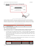
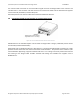
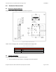
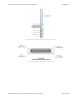
Figure5‐3ConnectortoTopBottomAntenna
One bottom‐located an tenna should be connected to the right‐side female SMA con nector shown in Figure
5‐3. Whenever power is supplied to the MXR, a 50‐ohm load should be provided to both SMA con nect ions.
Ensure that the antenna selected provide a 50‐ohm termination for the MXR. Install
a 50‐ohm termination
ratedfor5WminimumintheunusedSMAFemaleTopAntennaConnector.
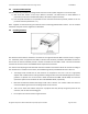
TheantennausedbyRangeFindershouldbemountedoutsideonthebottom‐sideoftheaircraftaccordingto
themanufacturer’sinstallationinstructi o ns, withadditionalguidanceprovidedbelowandinTable5‐4:
The Range Finder should have its own antenna. An exception to this rule is use of a high‐quality
diplexerthatenablesantennasharingbetweenaRangeFinderandcertainADS‐Bequipment.Further
guidance on diplexer use can be found in RTCA documents DO‐282B and DO‐260B, the minimum
operationalperformancestandardsforUATand1090MHzADS‐B,respectively.
Minimize the distance between the Range Finder and its antenna. The antenna cable must have no
morethan2dBofsignallossfromtheRangeFindertotheantenna.
Take care to locate the antenna away from
any objects that may disrupt the ground plane for the
antennas,suchasdoorsandlandinggear.
Donotplacetheantennaclosetoengineexhaust.