
System Description

SystemDescriptionandInstallationManualforRangeFinder ICD10000‐01
©SagetechCorporation2018ConfidentialProprietaryExportControlled Page13of130
5.2 RoutepowercablesandHostComputertotheRangeFinder
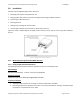
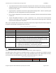
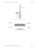
Figure5‐251‐PinMicroD‐SubTypeFemaleMainConnector
TheMainConnectorcarriespoweraswellasserialandEthernetcommunicationstothehostcomputer.
RangeFinder’sMainConnectorisa51‐pinMicroD‐Subtypefemaleconnector.Figure5‐2showstheMain
Connectorpinassignmentorientation.Table5‐2providestheMainConnectormanufacturer’spartnumber.
Table5‐2MainConnectorPartDescription
PartDescription Manufacturer PartNumber
FemalePowerandInterfaceConnector
Micro‐D51pin,2‐row
Omnetics A99601‐512
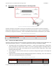
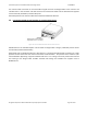
5.2.1 ConnecttotheMainConnector
Construct a cable to connect the host computer to the Main Connector according to pin‐outdefinitions and
instructionsdescribedinSection7.1.ThecableshouldbebuiltaccordingtostandardA‐A59569A.
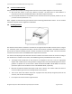
The Range Finder can be powered with 14‐28 VDC +/‐ 4 VDC (at the Range
Finder). Range Finder
power consumption is documented in Table 5‐3. If you are supplying voltage to the Range Finder at
the lower end of that range, avoid voltage loss by using short power supply wires and/or larger
diameterpowersupplywires.
Zener diodes are used on the DC
Power pins to protect the Range Finder against overvoltage and
reversepolarity.
Surgecurrentscanbe upto5Awhenenablingoperatingmodeortransmitting.Thein‐rushcurrentat
power‐on(inoperatingmode)willalsonotexceed5A.
Table5‐3MaximumCurrentConsumption
Variant
SupplyVoltage
MaxAverageCurrent Note
RangeFinder 14V 2.1A Measured
28V 1.0A Measured