System Description and Installation Manual for Range Finder ICD10000‐01 May 2018 © © Sagetech Corporation 2018 Proprietary Confidential Export‐controlled
System Description and Installation Manual for Range Finder ICD10000‐01 Contents Contents ................................................................................................................................................... 2 1.0 List of Tables ................................................................................................................................. 4 2.0 List of Figures ................................................................................................
System Description and Installation Manual for Range Finder ICD10000‐01 8.3.4 Operating Message: Type 0x03 ....................................................................................... 36 8.3.5 GPS Navigation Data Message: Type 0x04 ...................................................................... 40 8.3.6 Data Request Message: Type 0x05 .................................................................................. 46 8.3.7 Target Request Message: Type 0x0B .............................
System Description and Installation Manual for Range Finder 1.0 ICD10000‐01 LIST OF TABLES Table 5‐1 Common mounting parts/vendors ....................................................................................................... 12 Table 5‐2 Main Connector Part Description ......................................................................................................... 13 Table 5‐3 Maximum Current Consumption .................................................................................
System Description and Installation Manual for Range Finder ICD10000‐01 Table 8‐36 Flight ID Response Message Example Data ........................................................................................ 59 Table 8‐37 Status Response Message Payload Structure Overview .................................................................... 60 Table 8‐38 Status Response Message Payload Structure Detail ..........................................................................
System Description and Installation Manual for Range Finder 2.0 ICD10000‐01 LIST OF FIGURES Figure 5‐1 Range Finder Feature Locations .......................................................................................................... 11 Figure 5‐2 51‐Pin Micro D‐Sub Type Female Main Connector ............................................................................. 13 Figure 5‐3 Connector to Top Bottom Antenna ...................................................................................
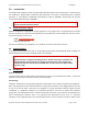
System Description and Installation Manual for Range Finder 3.0 ICD10000‐01 Introduction The Range Finder Interface Control Document (ICD) describes Range Finder characteristics, communications and installation. Range Finder functionality and performance are meant to demonstrate basic TCAS‐like operation; i.e., interrogation at 1030 MHz and listening for replies at 1090 MHz. Range Finder also receives and transmits ADS‐B messages at 1090 MHz. NOTE: This document is under development.
System Description and Installation Manual for Range Finder ICD10000‐01 determined by turning the equipment off and on, the user is encouraged to try to correct the interference by one or more of the following measures: • Reorient or relocate the receiving antenna • Increase the separation between the equipment and receiver • Connect the equipment into an outlet on a circuit different from that to which the receiver is connected. • Consult the dealer or an experienced radio/TV technician for help.
System Description and Installation Manual for Range Finder 4.0 ICD10000‐01 Overview The Range Finder is a small device capable of locating aircraft in its immediate area and determining ranges. Range Finder is a member of the Sagetech MX product family. Range Finder performs the following basic functions: Range Finding: o Sends out “all‐call” (broadcast) interrogations, listens to replies and reports the information, including range, to the command and control interface.
System Description and Installation Manual for Range Finder 4.1 ICD10000‐01 Range Finder includes an internal pressure altitude sensor, encoder and an altitude encoder port to a static pressure line. The integral altitude encoder is calibrated to 60,000 feet MSL by default. Configurations are available with calibration/defined altitude error up to 100,000 feet MSL. Its approximate dimensions are 3.3” x 2.4” x 0.9”. (See Figure 6‐1.) Operating temperature is designed to be ‐40 to +71°C when 2.
System Description and Installation Manual for Range Finder 5.0 ICD10000‐01 Installation Installation of the Sagetech Range Finder consists of: Mounting with required 2.
System Description and Installation Manual for Range Finder ICD10000‐01 Range Finder should be mounted away from sources of excess heat to better guarantee an operating environment within its designed temperature range. The Range Finder requires a 2.0°C/Watt heat sink at full power above 40°C ambient. Actual heat sink needs are dependent on temperature of operating environment and power load. Range Finder is designed in such a way that its case conducts thermal load to the aircraft frame.
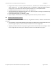
System Description and Installation Manual for Range Finder 5.2 ICD10000‐01 Route power cables and Host Computer to the Range Finder Figure 5‐2 51‐Pin Micro D‐Sub Type Female Main Connector The Main Connector carries power as well as serial and Ethernet communications to the host computer. Range Finder’s Main Connector is a 51‐pin Micro D‐Sub type female connector. Figure 5‐2 shows the Main Connector pin assignment orientation. Table 5‐2 provides the Main Connector manufacturer’s part number.
System Description and Installation Manual for Range Finder 5.3 ICD10000‐01 Connect to GPS Interface GPS data should be provided to the Range Finder from the aircraft system integrator in one of two ways: a) GPS serial data stream on the 51‐pin Micro‐D connector. The data format is either NMEA or a proprietary format from a NexNav Mini GPS (a TSO‐C145c compliant solution). b) Host Computer GPS data is incorporated into the command and control protocol packets on the 51‐ pin serial interface.
System Description and Installation Manual for Range Finder ICD10000‐01 Try to keep the antennas located at least 36” away from other antennas on the aircraft. The antennas should be located as close to the centerline of the fuselage as space allows, while trying to keep the antennas on a flat surface. A ground plane is required for most antennas appropriate for Range Finder. Failure to provide a good ground plane can result in degradation of antenna performance.
System Description and Installation Manual for Range Finder ICD10000‐01 The antenna cable must have no more than 2dB of signal loss from the Range Finder to the antenna. This includes losses in the connector and cable. Generic and custom‐built cables can be obtained from suppliers such as Pasternak, Richardson, and Aircraft Spruce. Avoid sharp bends in the antenna cable that could lead to additional cable loss. 5.
System Description and Installation Manual for Range Finder 6.0 ICD10000‐01 Mechanical Characteristics 6.1 Dimension, Weight & Material Range Finder’s width, height, and length are shown in Figure 6‐1. Figure 6‐1 Range Finder Dimensions Table 6‐1 lists the weight, color, and material attributes of the Range Finder. Table 6‐1 Mechanical Attributes Mechanical Attributes Weight: 150g Color: Black Plating: Electroless Black Nickel 6.
System Description and Installation Manual for Range Finder ICD10000‐01 Two Transponder/ADS‐B L‐Band SMA antenna connectors. Only the bottom antenna connector is used by Range Finder. See the Bottom Antenna connector in Figure 6‐2, located on lower right side when facing main connector. One Pressure Altitude Sensor/Encoder port to static pressure, connected to tubing with a clamped diameter of 0.18”. The locations of these connectors/ports are shown in Figure 6‐2.
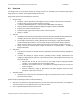
System Description and Installation Manual for Range Finder ICD10000‐01 Figure 6‐3 Range Finder Main Connector (Female) Pin Locations Figure 6‐4 Range Finder Main Connector ‐ Front View © Sagetech Corporation 2018 Confidential Proprietary Export Controlled Page 19 of 130
System Description and Installation Manual for Range Finder 7.0 ICD10000‐01 Electrical Characteristics 7.1 Main Connector The electrical interface consists of signals brought to the Range Finder via the 51‐Pin Micro‐D main connector. Figure 6‐4 presents an image of the female Micro D‐Sub Main Connector’s front view, with pin number orientation. Table 7‐1 shows the pin assignments for the main connector.
System Description and Installation Manual for Range Finder ICD10000‐01 Table 7‐1 Main Connector Pin Assignments Pin Number Signal Direction Signal Char.
System Description and Installation Manual for Range Finder Pin Number Signal ICD10000‐01 Direction Signal Char.
System Description and Installation Manual for Range Finder ICD10000‐01 Table 7‐2 Communication Port Select Map Serial Bus Type/ Required Configuration Main Connector Interface Signal Pin RS‐422 Com0 Com0‐RX‐ 44 Com0‐Mode pin 17 should be left open Com0‐RX+ 19 Com0‐TX‐ 45 Com0‐TX+ 20 Com0‐Mode 17 RS‐232 Com0 Com0‐232‐RX 19 Com0‐Mode pin 17 must be tied to ground Com0‐232‐TX 20 Com0‐Mode 17 RS‐422 Com1 Com1‐RX‐ 46 Com0‐Mode pin 43 can be left open Com1‐RX+ 21 Com1‐TX‐ 47 Com
System Description and Installation Manual for Range Finder 8.0 8.1 ICD10000‐01 Host Interface Characteristics Communications Range Finder is controlled by a straightforward messaging system which communicates over a serial or Ethernet interface. Communicating with the Range Finder involves constructing messages, computing a checksum to ensure data validity, and sending these messages to the Range Finder. 8.1.
System Description and Installation Manual for Range Finder ICD10000‐01 Table 8‐2 Packet Structure Message Field Field Description Start Byte Message Type Message ID Precedes all messages with a fixed value of 0xAA. Defines the message type. Contains an arbitrary number between 0 and 255 (inclusive) that uniquely identifies the message. (Typically, a sequence number.) Acknowledgement messages include the Message ID of the command message being acknowledged.
System Description and Installation Manual for Range Finder 8.3 ICD10000‐01 Messages Sent to the Range Finder 8.3.1 Overview Table 8‐3 provides an overview of the command messages that can be sent to the Range Finder. Table 8‐3 Messages Received by the Range Finder Range Finder Response 0x01 Payload Length (Bytes) 36 ACK + Message Once at installation Flight ID 0x02 12 ACK + Message 8.3.
System Description and Installation Manual for Range Finder ICD10000‐01 8.3.2 Installation Message: Type 0x01 This message contains information about the aircraft and its capabilities. This information is stored in non‐ volatile memory and needs to be sent only once at installation time. Table 8‐4 provides an overview of the payload structure for the Installation Message. Table 8‐5 provides a detailed description of the Installation Message payload.
System Description and Installation Manual for Range Finder ICD10000‐01 Aircraft Registration Byte Offset Byte Name Field Description 03 AR0 AR0 AR1 AR2 AR3 AR4 AR5 AR6 Aircraft Registration 04 AR1 0x31 0x32 0x33 0x33 0x30 0x32 0x01 1233021 05 AR2 Aircraft Registration Bytes Set 56‐bit Aircraft Registration. This can be the tail number or registration number. Up to seven ASCII characters can be entered.
System Description and Installation Manual for Range Finder ICD10000‐01 COM Port 1 Byte Offset Byte Name Field Description 13 C10 Byte C10 0x00 0x01 0x02 0x03 0x04 0x05 0x06 0x07 0x08‐0xFF Bit value 38400 Bits per Second (Default) 600 Bits per Second 4800 Bits per Second 9600 Bits per Second 28800 Bits per Second 57600 Bits per Second 115200 Bits per Second 230400 Bits per Second Reserved If a baud rate change is requested of the same port that the Installation Message was received on, the change w
System Description and Installation Manual for Range Finder ICD10000‐01 GPS Integrity9 Byte Offset 24 Byte Name GI0 Field Description Source Integrity Level (SIL) The GPS SIL should be set by a qualified expert. The field is used to declare the probability of the horizontal position exceeding the radius of containment defined by the NIC without alerting. As a guideline, Low integrity should be set for VFR only GPS or an uncertified installation.
System Description and Installation Manual for Range Finder Emitter Category Byte Offset Byte Name 26 EC0 Field Description Byte EC0 0x00 0x01 0x02 0x03 0x04 0x05 0x06 0x07 0x08‐0xFF Byte EC0 0x00 0x01 0x02 0x03 0x04 0x05 0x06 0x07 0x08‐0xFF Byte EC0 0x00 0x01 0x02 0x03 0x04 0x05 0x06‐0xFF Byte EC0 0x00 0x01‐0xFF ICD10000‐01 Set A (ES0=0x00) Categories Unknown Light (<15500 lbs.) Small (15500 to 75000 lbs.) Large (75000 to 300000 lbs.) High‐Vortex Large (aircraft such as B‐757) Heavy (> 300000 lbs.
System Description and Installation Manual for Range Finder Aircraft Size Byte Offset Byte Name 27 AS0 ICD10000‐01 Field Description AS0 Bit Position Aircraft Size Length (m) Unknown‐Default <= 15 <= 25 <= 25 <= 35 <= 35 <= 45 <= 45 <= 55 <= 55 <= 65 <= 65 <= 75 <= 75 <= 85 <= 85 Reserved 0x00 0x01 0x02 0x03 0x04 0x05 0x06 0x07 0x08 0x09 0x0A 0x0B 0x0C 0x0D 0x0E 0x0F 0x10‐0xFF Width (m) Unknown‐Default <= 23 <= 28.5 <= 34 <= 33 <= 38 <= 39.5 <= 45 <= 45 <= 52 <= 59.5 <= 67 <= 72.
System Description and Installation Manual for Range Finder ICD10000‐01 Reserved Byte Offset Byte Name 31 RE2 Field Description This field is reserved for future use. Set to ZERO. All other values are invalid.
System Description and Installation Manual for Range Finder ICD10000‐01 Table 8‐6 Installation Message Example Data Message Field Byte Values (original) Byte Message Content (Hex) Start Byte AA [ AA ] Message Type 0x01 Installation Message [ 01 ] Message ID An arbitrary number between 0 and 255 (inclusive) that uniquely identifies the message.
System Description and Installation Manual for Range Finder ICD10000‐01 8.3.3 Flight ID Message: Type 0x02 The Flight ID Message sets the Flight ID and, if used, it should be sent at least once every 5 seconds. If the Flight ID is not received for 10 seconds, the transponder defaults to using the aircraft registration sent in the Installation Message. This message is not commonly sent. Note: It is not a requirement to use the Flight ID message. An overview of the Flight ID Message is shown in Table 8‐7.
System Description and Installation Manual for Range Finder ICD10000‐01 Table 8‐9 Flight ID Message Example Data PAYLOAD Message Field Byte Values (original) Byte Message Content (Hex) Start Byte AA [ AA ] Message Type 0x02 Flight ID Message [ 02 ] Message ID An arbitrary number between 0 and 255 (inclusive) that uniquely identifies the message.
System Description and Installation Manual for Range Finder ICD10000‐01 Table 8‐11 Operating Message Payload Structure Detail Squawk Code Byte Offset Byte Name Field Description 00 SQK0 01 SQK1 Mode A “Squawk” Code – A string of 4 3‐bit (octal) numbers, padded with 4 leading zeros.
System Description and Installation Manual for Range Finder ICD10000‐01 Altitude Byte Offset Byte Name Field Description 04 ALT0 Altitude 05 ALT1 Altitude bit field definition is as follows: Bits 0‐13 Altitude Data The aircraft barometric altitude is measured with reference to a pressure of 29.9213” Hg. The data is an unsigned integer, offset by 1200 feet, in units of 25 or 100 feet (as defined in the Installation Message). Altitude values outside of ‐1200 to 126,700 feet are invalid.
System Description and Installation Manual for Range Finder ICD10000‐01 Heading Byte Offset Byte Name 08 HDG0 09 HDG1 Field Description The Heading field units and resolution are specified as a fraction of a circle. ie. .5 = 180°, .25 = 90°, etc. Bit 15 Heading Valid Bits 14 ‐ 0 Heading units and resolution Most significant bit = .5, the next .25, the next .125, etc. Examples: 0x8000 0x9000 0xA000 0xC000 0xD000 0xF000 0° valid (.0 * 360) 45° valid (.125 * 360) 90° valid (.25 * 360) 180° valid (.
System Description and Installation Manual for Range Finder ICD10000‐01 8.3.5 GPS Navigation Data Message: Type 0x04 The GPS Data Message: Provides the Range Finder with GPS data, including ‐ latitude, longitude, height, groundspeed, track, and validity, accuracy and integrity measurements. If used, should be sent at regular intervals (between one and five times per second), typically at the nominal update rate of the GPS hardware.
System Description and Installation Manual for Range Finder ICD10000‐01 Table 8‐14 GPS Navigation Data Message Payload Structure Detail GPS Longitude Byte Offset 00 Byte Name LON0 Field Description 01 LON1 02 LON2 LON 0 0x31 0x30 0x31 03 LON3 ...
System Description and Installation Manual for Range Finder ICD10000‐01 Speed Over Ground Byte Offset 21 Byte Name SOG0 Field Description 22 SOG1 23 SOG2 24 SOG3 25 SOG4 Speed Over Ground 26 SOG5 Current GPS speed over ground in knots. The data is sent as ASCII characters. Note that two formats are available, in order to support supersonic or subsonic operations: ssss.s or sss.
System Description and Installation Manual for Range Finder ICD10000‐01 Hemisphere/Data Status Byte Offset 35 Byte Name GHB0 Field Description GHB0 Hemisphere and GPS Data Status 0x00 S hemisphere, W hemisphere; No SVERROR fault, GPS data is valid 0x01 N hemisphere, W hemisphere; No SVERROR fault, GPS data is valid 0x82 S hemisphere, E hemisphere; No SVERROR fault, GPS data is invalid 0x03 N hemisphere, E hemisphere; No SVERROR fault, GPS data is valid 0x43 N hemisphere, E hemisphere; SVERROR fault, G
System Description and Installation Manual for Range Finder ICD10000‐01 GPS Height (WGS‐84) Byte Offset 46 47 48 49 Byte Name HT0 HT1 HT2 HT3 Field Description GPS Height (WGS‐84) All zeros – Altitude not available Else Floating point Height (meters) Above WGS‐84 ellipsoid Horizontal Protection Limit (HPL) Byte Offset 50 51 52 53 Byte Name HP0 HP1 HP2 HP3 Field Description Horizontal Protection Limit (HPL) All zeros – HPL not available Else Floating point radius (meters) of a circle centered on the t
System Description and Installation Manual for Range Finder ICD10000‐01 Table 8‐15 GPS Navigation Data Message Example Data Message Field Byte Values (original) Byte Message Content (Hex) Start Byte Message Type AA 0x04 GPS Data Message AA Message ID An arbitrary number between 0 and 255 (inclusive) that uniquely identifies the message. 12 04 PAYLOAD Payload Length 63 3F Longitude 4543.6632Degrees [ 31 32 31 32 39 2E 31 32 34 38 30 ] Latitude 12129.
System Description and Installation Manual for Range Finder ICD10000‐01 8.3.6 Data Request Message: Type 0x05 This message is a request for the Range Finder to send data in a response message. The type of data being requested is specified in the payload of this message, which consists of a single byte that specifies the response message type. In response to a valid Data Request Message, the Range Finder sends an Acknowledge Message immediately followed by a response message.
System Description and Installation Manual for Range Finder Checksum ICD10000‐01 8‐bit arithmetic sum of message from Start Byte to last byte of the Payload Data. [ 39 ] 8.3.7 Target Request Message: Type 0x0B This message is used to request data on ADS‐B, TIS‐B and ADS‐R targets being tracked by the Range Finder. An over view of the Target Request Message is shown in Table 8‐19. Table 8‐20 provides the detailed message definition. An example of message content is found in Table 8‐21.
System Description and Installation Manual for Range Finder ICD10000‐01 Participant ID Byte Offset Byte Name Field Description 03 ID0 ID0 ID1 ID2 Participant ID 04 ID1 0x00 0x01 0x02 000102 05 ID2 0x03 0xFE 0x14 03FE14 Participant ID ICAO Address for Request Type 2 Requested Reports Byte Offset Byte Name 06 RR0 Field Description Report Transmit Requested (Bit value of 1 = Transmit) Bit 0 1 2 3 4 5 6 7 Requested Reports State Vector or Coarse Position Reports Mode Status Target S
System Description and Installation Manual for Range Finder ICD10000‐01 8.3.8 Mode Message: Type 0x0C The Mode Message is sent to the Range Finder to enable/disable modes or set mode data values. The current settings of the mode enable/disable flags and the mode data values can be obtained by using the Data Request Message to send the Mode Settings Message. An overview of the Mode Message is shown in Table 8‐22. Table 8‐23 provides details for the message structure. Table 8‐24 shows example message data.
System Description and Installation Manual for Range Finder ICD10000‐01 8.3.9 Interrogation Command Message: Type 0xA0 The Interrogation Command is a message from Host Computer to the Range Finder sent to start the interrogation output. The payload contains six bytes. The first byte commands the interrogation off or sets the type of interrogation.
System Description and Installation Manual for Range Finder ICD10000‐01 Interrogation Amplitude Byte Offset Byte Name 01 AMPL0 Field Description Byte Value Decimal Amplitude 0x09 9 dBm 0x0A 10 dBm 0x0B 11 dBm 0x0C 12 dBm 0x0D 13 dBm … … 0x36 54 dBm 0x37 55 dBm 0x38 ‐ 0xFF Not Allowed Value of Amplitude. Antenna Select Byte Offset 02 Byte Name ANT0 Field Description Bit Position 0x00 0x01 0x02 Antenna Select Installed antenna. (Bottom, if both are installed.
System Description and Installation Manual for Range Finder ICD10000‐01 Table 8‐27 provides an overview of the payload structure for the Whisper Shout Interrogation Command Message. Table 8‐28 provides a detailed description of the Whisper Shout Interrogation Command Message payload.
System Description and Installation Manual for Range Finder ICD10000‐01 Whisper Shout Step Size Byte Offset 02 Byte Name SS0 Field Description Bit Position Whisper Shout Interrogation Type 0x00 Not Allowed 0x01 1dB 0x02 2dB … … 0x0E 14 dB 0x0F 15 dB 0x10‐0xFF Reserved This value is the power attenuation for each step in the Whisper Shout sequence.
System Description and Installation Manual for Range Finder 8.4 ICD10000‐01 Messages Sent from the Range Finder 8.4.1 Overview Table 8‐29 lists the message types the Range Finder can send. Table 8‐29 Messages Sent from the Range Finder Message Name Message Type Payload Length (Bytes) Document Section Acknowledge 0x80 6 8.4.2 Installation Response 0x81 36 8.4.3 Flight ID Response 0x82 12 8.4.4 Status Response 0x83 6 8.4.5 Reserved 0x84‐85 Mode Settings Message 0x8C 5 8.4.
System Description and Installation Manual for Range Finder ICD10000‐01 8.4.2 Acknowledge Message: Type 0x80 The Acknowledge Message (ACK) is sent by the Range Finder to indicate that a message was received in the correct format and with valid data. The Range Finder performs range checking on all incoming data. If any data is invalid the message is ignored and the Range Finder does not ACK. This message: Is sent after every receipt of a valid message. Contains Range Finder status information.
System Description and Installation Manual for Range Finder ICD10000‐01 ACK’d Message ID Byte Offset 01 Byte Name AMTI Field Description AMTI ACK’d Message ID 0x00 0x01 … [ 0000 0000 ] [ 0000 0001 ] ... ACK’d Message ID Contains the Message ID of the message being acknowledged. System State Byte Byte Offset 02 Byte Name SSB0 Field Description SSB0 System State Byte indicates current Range Finder State Information Bit 0 Range Finder Fail Flag 1 = an error within the Range Finder.
System Description and Installation Manual for Range Finder ICD10000‐01 Table 8‐32 Acknowledge Message Example Data Message Field Byte Values (original) Byte Message Content (Hex) Start Byte Message Type Message ID Payload Length ACK’d Message Type AA 0x80 Acknowledge Message An arbitrary number between 0 and 255 (inclusive) that uniquely identifies the message.
System Description and Installation Manual for Range Finder ICD10000‐01 Payload Index Message Field Number bytes 31 ADS‐B Out DF 1 33 Install Configuration 1 34 Reserved 2 Table 8‐34 Installation Response Message Example Data Message Field Byte Values (original) Byte Message Content (Hex) Start Byte AA [ AA ] Message Type 0x81 Installation Message Response [ 81 ] Message ID An arbitrary number between 0 and 255 (inclusive) that uniquely identifies the message.
System Description and Installation Manual for Range Finder ICD10000‐01 8.4.4 Flight ID Response Message: Type 0x82 The Flight ID Response Message is sent in response to a Flight ID Message (0x02) or to a Data Request Message (0x05) that specifies a Requested Message Type of 0x82. This message contains the Flight ID, stored in volatile memory from the last valid Flight ID Message; if a Flight ID Message has not been received for 10 seconds, then all fields in this message are set to all ZEROs (0x00).
System Description and Installation Manual for Range Finder ICD10000‐01 8.4.5 Status Response Message: Type 0x83 The Status Response Message is sent in response to a Data Request Message that specifies a Requested Message Type of 0x83. This message contains the software and complex hardware (i.e., firmware) versions of the Range Finder, the checksum of the SW image and the results of the Built‐In Tests (BITs). The Power‐On BIT is executed once when the Range Finder is powered on and power is stable.
System Description and Installation Manual for Range Finder ICD10000‐01 SW Image Checksum (CRC) Byte Offset Byte Name 02 03 04 05 CRC0 CRC1 CRC2 CRC3 Byte Offset Byte Name Field Description SW Image Checksum: 32‐bit checksum of the SW Image.
System Description and Installation Manual for Range Finder ICD10000‐01 Table 8‐39 Status Response Message Example Data Message Field Byte Values (original) Byte Message Content (Hex) Start Byte AA [ AA ] Message Type 0x83 Status Response Message [ 83 ] PAYLOAD Message ID An arbitrary number between 0 and 255 (inclusive) that uniquely identifies the message.
System Description and Installation Manual for Range Finder ICD10000‐01 Table 8‐42 Version Response Message Payload Structure Detail Software Version Byte Offset 00 Byte Name Field Description SWV0 SWV0 SW Version 0x01 SW version 1 0x02 SW version 2 … … SW Version Contains the software version of the Range Finder.
System Description and Installation Manual for Range Finder ICD10000‐01 Table 8‐43 Version Response Message Example Data PAYLOAD Message Field Byte Values (original) Byte Message Content (Hex) Start Byte AA [ AA ] Message Type 0x8E Version Response Message [ 8E ] Message ID An arbitrary number between 0 and 255 (inclusive) that uniquely identifies the message.
System Description and Installation Manual for Range Finder ICD10000‐01 8.4.8 ADS‐B In Report Message Overview Extended Squitters messages received by the Range Finder report Position, Velocity, Identification and Category, Target State and Status, and Aircraft Operational Status. From this data, Range Finder generates ADS‐B, TIS‐B and ADS‐R reports for delivery to the flight computer which communicates the data to the user.
System Description and Installation Manual for Range Finder 8.4.8.1 ICD10000‐01 Target Summary Report Message: Type 0x90 When a Target Request Message (Type 0x0B) Type 1 (Request Target Summary) is received, a Target Summary Report in is transmitted. The report lists the nearest N targets (with N specified in the Target Request Message) in range order. An overview of the Target Summary Report Message is shown in Table 8‐45. Table 8‐46 provides the detailed message definition.
System Description and Installation Manual for Range Finder 8.4.8.2 ICD10000‐01 ADS‐B State Vector Report Message: Type 0x91 The ADS‐B State Vector Report Message is one of several message types sent by Range Finder to report data on a particular ADS‐B In participant. The ADS‐B State Vector Report Message contains information about a specific ADS‐B participant.
System Description and Installation Manual for Range Finder ICD10000‐01 Table 8‐48 ADS‐B State Vector Report Message Payload Structure Detail Report Type and Structure ID Byte Offset Byte Name Field Description 00 RS0 RS0 (MSN) RS0 (LSN) RS1 RS2 Report Type and Structure ID 01 RS1 0x1 0xF 0xCF 0x98 State Vector Report for Airborne Target Omitting GS and HDG on surface, and estimated velocity.
System Description and Installation Manual for Range Finder ICD10000‐01 Validity Flags Byte Offset Byte Name 03 VF0 04 VF1 Field Description Byte VF0 VF1 Bit Data Field(s) 7 6 5 4 3 2 1 0 7 6 0‐5 Latitude and Longitude Altitude, Geometric N/S and E/W Velocity Ground Speed while on Surface Heading while on the Surface Altitude, Barometric Vertical Rate, Geometric Vertical Rate, Barometric Estimated Latitude and Longitude Estimated N/S and E/W Velocity Reserved Validity Flags These flags indicat
System Description and Installation Manual for Range Finder ICD10000‐01 Report Times of Applicability Byte Offset Byte Name Field Description 09 RA0 RA0 RA1 RA2 RA3 RA4 RA5 Reported Time of Applicability 10 RA1 00x00 0x58 00x00 0x70 0x00 0x80 11 RA2 Estimated Position and Velocity: 0.6875 seconds Position: 0.875 seconds Velocity: 1.000 seconds 12 RA3 0x28 0x30 0x28 0x52 0x28 0x60 13 RA4 Estimated Position and Velocity: 80.375 seconds Position: 80.641 seconds Velocity: 80.
System Description and Installation Manual for Range Finder ICD10000‐01 Longitude Byte Offset Byte Name Field Description 18 EG0 EG0 EG1 EG2 Longitude 19 EG1 20 EG2 0xA0 0x80 0x04 0x00 0x28 0x25 0x80 0x60 0x09 ‐134.997253 Degrees ‐179.778214 Degrees 5.828440 Degrees Longitude The data is sent in the following format: SMdddddd dddddddd dddddddd The S bit indicates whether the data is positive (East) or negative (West).
System Description and Installation Manual for Range Finder ICD10000‐01 East/West Velocity Byte Offset Byte Name Field Description 26 EW0 EW0 27 EW1 0x00 0x07 0xFF EW1 0xD9 0x15 0x00 East/West Velocity 27.13 Knots 226.63 Knots ‐32.00 Knots East/West Velocity Format the E/W Velocity in the target’s State Vector into a 16‐bit 2’s complement number (SMdddddddddddddL, where S=0 for east and 1 for west, M = 2048 knots, and L = 0.
System Description and Installation Manual for Range Finder ICD10000‐01 Barometric Altitude Byte Offset 30 31 32 Byte Name BA0 BA1 BA2 Field Description BA0 0x20 0x01 0xFF BA1 0x00 0x28 0xC7 BA2 0x80 0x30 0xC0 Barometric Altitude 32,770 Feet 1,184.75 Feet ‐225 Feet Barometric Altitude The data is sent in the following format: Sddddddd dddddddd dddddddd The S bit indicates whether the data is positive or negative.
System Description and Installation Manual for Range Finder ICD10000‐01 Estimated Latitude Byte Offset 36 37 38 Byte Name LE0 LE1 LE2 Field Description LE0 0x0F 0xF9 0xDF LE1 0x1C 0x99 0x77 LE2 0x71 0x99 0x77 Estimated Latitude 21.249983 Degrees ‐9.000013 Degrees ‐45.750010 Degrees Estimated Latitude Latitude position is estimated when an Airborne Velocity message is received.
System Description and Installation Manual for Range Finder ICD10000‐01 Surveillance Status Byte Offset 46 Byte Name SS0 Field Description SS0 (MSN) Surveillance Status 0x0 No Condition Information Available 0x2 Permanent Alert Condition (Emergency) 0x4 Temporary Alert Condition (Change in Mode Identity Code other than emergency condition) 0x6 Special Position Identification (SPI) Condition 0x7‐0xF Reserved SSO (LSN) Intent Change Flag 0x0 No Change in Intent 0x1 Reserved 0x2 Intent Change 0x3‐0xF Res
System Description and Installation Manual for Range Finder ICD10000‐01 Table 8‐49 ADS‐B State Vector Report Message Example Data PAYLOAD Message Field Byte Values (original) Byte Message Content (Hex) Start Byte Message Type Message ID Payload Length Report Type and Structure ID Validity Flags Participant Address Address Qualifier Report Times of Applicability Lat Long Geometric Altitude N/S Velocity E/W Velocity Barometric Altitude Vertical Rate NIC Estimated Latitude Estimated Longitude Surveillan
System Description and Installation Manual for Range Finder 8.4.8.3 ICD10000‐01 ADS‐B Mode Status Report Message: Type 0x92 The ADS‐B Mode Status Report Message is one of several message types sent by Range Finder to report data on a particular ADS‐B In participant. The ADS‐B Mode Status Report Message: Is sent for aircraft/vehicles being monitored by the Range Finder as specified in the Target Request Message (type 0x0B).
System Description and Installation Manual for Range Finder ICD10000‐01 Table 8‐51 ADS‐B Mode Status Report Message Payload Structure Detail Report Type and Structure ID Byte Offset Byte Name 00 RS0 01 RS1 02 RS2 Field Description RS0 (MSN) 0x2 0x2 0x2 0x2 0x2 RS0 (LSN) 0xF 0xF 0xF 0xF 0xF RS1 RS2 Report Type and Structure ID 0x6E 0x7E 0xFE 0x7F 0xFF 0x60 0xE0 0xE0 0xE0 0xE0 Version 0 TargetVersion 1 Airborne Target Version 1 Surface Target Version 2 Airborne Target Version 2 Surface Targe
System Description and Installation Manual for Range Finder ICD10000‐01 Participant Address Byte Offset Byte Name 04 05 06 Field Description PA0 PA1 PA2 PA0 PA1 PA2 Participant Address 0x1C 0xA6 0xB2 1CA6B2 0x2A 0x35 0x6A 2A356A Participant Address Bytes Contains the address of the transmitting installation. These fields contain up to 6 hex characters. This can be the ICAO address or some other type of address.
System Description and Installation Manual for Range Finder ICD10000‐01 Emitter Category Byte Offset 19 Byte Name Field Description EC0 EC0 Emitter Category 0x00 No Emitter Category Information Available 0x01 Light (<15500 lbs.) 0x02 Reserved 0x03 Small (15500 to 75000 lbs.) 0x04 Reserved 0x05 Large (75000 to 300000 lbs.
System Description and Installation Manual for Range Finder ICD10000‐01 Emergency/Priority Status Byte Offset 21 Byte Name EP0 Field Description EP0 0x00 0x01 0x02 0x03 0x04 0x05 0x06 0x07‐0xFF Emergency/Priority Status No Emergency General Emergency Lifeguard/medical Emergency Minimum Fuel No Communications Unlawful Interference Downed Aircraft Reserved Capability Class Codes Byte Offset 22 23 24 Byte Name CC0 CC1 CC2 Field Description Byte CC0 Bit Capability Class Codes 4‐7 Reserved 3 B2 Low – In
System Description and Installation Manual for Range Finder ICD10000‐01 Operational Mode Byte Offset 25 26 Byte Name OM0 OM1 Field Description Byte Bit Operational Mode OM0 7 OM Format – Set to “ZERO” to indicate the formatting below. 6 OM Format – Set to “ZERO” to indicate the formatting below.
System Description and Installation Manual for Range Finder ICD10000‐01 SV Quality ‐ NACv Byte Offset 28 Byte Name NV0 Field Description NV0 0x00 0x01 0x02 0x03 0x04 0x05‐0xFF SV Quality – NACv. Horizontal Velocity Error Unknown or ≥10 m/s < 10 m/s < 3 m/s < 1 m/s < 0.3 m/s Reserved The NACv field reports the horizontal velocity error with 95% certainty.
System Description and Installation Manual for Range Finder ICD10000‐01 Track/Heading and HRD Byte Offset 32 Byte Name TH0 Field Description TH0 Track/Heading and Horizontal Reference Direction (HRD) 0x00 Ground track relative to true north being reported 0x01 Ground track relative to magnetic north reported 0x02 Heading relative to true north being reported 0x03 Heading relative to magnetic north being reported 0x04‐0xFF Reserved Track Heading and HRD This data indicates the nature of the horizontal di
System Description and Installation Manual for Range Finder 8.4.8.4 ICD10000‐01 ADS‐B Target State Report Message: Type 0x97 The ADS‐B Target State Report Message is one of several message types sent by Range Finder to report data on a particular ADS‐B In participant. The ADS‐B Target State Report Message: Is sent for aircraft/vehicles being monitored by the Range Finder as specified in the Target Request Message (type 0x0B).
System Description and Installation Manual for Range Finder ICD10000‐01 Table 8‐54 ADS‐B Target State Report Message Payload Structure Detail Report Type and Structure ID Byte Offset Byte Name 00 RS0 01 RS1 Field Description RS0 (MSN) 0x5 RS0 (LSN) 0xF RS1 Report Type and Structure ID 0xF8 Target State Report; All data fields are supported Report Type and Structure ID The Most Significant Nibble (MSN) of the byte RS0 contains the Report Type.
System Description and Installation Manual for Range Finder ICD10000‐01 Validity Flags Byte Offset Byte Name Field Description 02 VF0 Byte Bit Data Field(s) 03 VF1 VF0 0‐7 Reserved VF1 7 Selected Altitude 6 Barometric Pressure Setting 5 Selected Heading 4 MCP/FCU Mode 0‐3 Reserved Validity Flags These flags indicate whether or not the data contained in the specified field is valid or not. If the bit is set to “ONE” then the data field contains valid information.
System Description and Installation Manual for Range Finder ICD10000‐01 Report Time of Applicability Byte Offset Byte Name Field Description 08 RA0 RA1 RA0 09 RA1 0x00 0x28 0x80 0x60 Report Times of Applicability Time of Applicability: 1.0 seconds Time of Applicability: 80.75 seconds Report Times of Applicability The two bytes of this message (RA0 and RA1) contain the Report Times of Applicability. The data is formatted such that subfield is in seconds with a resolution of 1/128 seconds.
System Description and Installation Manual for Range Finder ICD10000‐01 Selected Heading Byte Offset Byte Name Field Description 15 SH0 SH0 SH1 Selected Heading 16 SH1 0x00 0x00 0x01 0x00 0x01 0xFF 0 degrees 0.703125 degrees 359.296875 degrees Selected Heading Selected heading is sent in the following format: d dddd dddd with the most significant 7 bits unused. Selected heading is sent in units of degrees with a resolution of 0.703125 degree.
System Description and Installation Manual for Range Finder ICD10000‐01 LNAV Mode Engaged Byte Offset 21 Byte Name Field Description LN0 LN0 LNAV Mode Engaged 0x00 LNAV Mode is not active or unknown 0x01 LNAV Mode is active 0x02‐0xFF Reserved LNAV Engaged Indicates whether or not lateral navigation mode is active. Reserved Byte Offset 22 8.4.8.5 Byte Name RE0 Field Description These bytes are reserved for future use and are not output by the Range Finder.
System Description and Installation Manual for Range Finder ICD10000‐01 Table 8‐56 ADS‐B Air Referenced Velocity Report Message Payload Structure Detail Report Type and Structure ID Byte Offset 00 01 Byte Name RS0 RS1 Field Description RS0 (MSN) 0x4 RS0 (LSN) 0x0 RS1 0x07 Report Type and Structure ID Air Referenced Velocity Report; All data fields are supported Report Type and Structure ID The Most Significant Nibble (MSN) of the byte RS0 contains the Report Type.
System Description and Installation Manual for Range Finder ICD10000‐01 Report Time of Applicability Byte Offset Byte Name 07 08 RA0 RA1 Field Description RA1 RA0 Report Time of Applicability 0x00 0x80 Time of Applicability: 1.0 seconds 0x28 0x60 Time of Applicability: 80.75 seconds Report Time of Applicability The two bytes of this message (RA0 and RA1) contain the report time of applicability. The data is formatted such that subfield is in seconds with a resolution of 1/128 seconds.
System Description and Installation Manual for Range Finder ICD10000‐01 8.4.9 TIS‐B Report Message Overview Like ADS‐B In Reports, TIS‐B In Reports are sent when position data becomes available for a TIS‐B participant and thereafter as participant data changes. If the position data for a TIS‐B participant has not been updated in 120 seconds, TIS‐B In Reports are no longer sent for that participant. Two types of targets are defined for TIS‐B: Fine Targets and Coarse Targets.
System Description and Installation Manual for Range Finder 8.4.9.2 ICD10000‐01 TIS‐B Mode Status Report Message: Type 0x94 The TIS‐B Mode Status Report Message is sent for TIS‐B participants transmitting fine format TIS‐B messages. For commonality with the ADS‐B Mode Status Report structure, the same Report Type and Structure Identification field is included in the TIS‐B Mode Status Report.
System Description and Installation Manual for Range Finder ICD10000‐01 Table 8‐59 TIS‐B Mode Status Report Message Payload Structure Detail Report Type and Structure ID Byte Offset Byte Name Field Description 00 RS0 RS0 (MSN) RS0 (LSN) RS1 RS2 01 RS1 0x0 0xB 0xCE 0x40 02 RS2 Report Type and Structure ID For commonality with the ADS‐B Mode Status Report structure, the Report Type and Structure Identification field is included in the TIS‐B Mode Status Report.
System Description and Installation Manual for Range Finder ICD10000‐01 Validity Flags Byte Offset Byte Name 03 VF0 Field Description Byte VF0 Bit Data Field(s) 6‐7 5 4 3 2 0‐1 Reserved SV Quality ‐ NACp SV Quality ‐ NACv SV Quality ‐ SIL Message Reserved2 Reserved Validity Flags These flags indicate whether or not the data contained in the specified field is valid or not. If the bit is set to “ONE” then the data field contains valid information.
System Description and Installation Manual for Range Finder ICD10000‐01 Call Sign Byte Offset Byte Name Field Description 10 CS0 CS0 CS1 CS2 CS3 CS4 CS5 CS6 CS7 Call Sign 11 CS1 0x4E 0x32 0x35 0x36 0x37 0x47 0x41 0x20 N2567GA 12 CS2 Call Sign 13 CS3 The Call Sign field indicates the aircraft identification used by the TIS‐B participant. Data is sent as unsigned char ASCII characters.
System Description and Installation Manual for Range Finder ICD10000‐01 Emitter Category Emitter Category Indicates the type of vehicle or aircraft TIS‐B participant. Message Reserved1 Byte Offset Byte Name 19 R10 Field Description Message Reserved1 This field contains the “Reserved” bits, “ME” bits 53‐56 from the Velocity Message subtypes 1 and 2 for GEO=0.
System Description and Installation Manual for Range Finder ICD10000‐01 SV Quality ‐ NACv Byte Offset Byte Name 22 Field Description NV0 NV0 Horizontal Velocity Error 0x00 Unknown or ≥10 m/s 0x01 < 10 m/s 0x02 < 3 m/s 0x03 < 1 m/s 0x04 < 0.3 m/s 0x05‐0xFF Reserved SV Quality ‐ NACv The NACv field reports the horizontal velocity error with 95% certainty.
System Description and Installation Manual for Range Finder ICD10000‐01 Track/Heading and Horizontal Reference Direction (HRD) Byte Offset 26 Byte Name Field Description TH0 TH0 0x00 0x01 0x02 0x03 0x04‐0xFF 8.4.9.
System Description and Installation Manual for Range Finder ICD10000‐01 Table 8‐61 TIS‐B Coarse Report Message Payload Structure Detail Participant Address Bytes Byte Offset Byte Name Field Description 00 PA0 PA0 PA1 PA2 Participant Address 01 PA1 02 PA2 0x1C 0x2A 0xA6 0x35 0xB2 0x6A 1CA6B2 2A356A Participant Address Bytes Contains the address of the transmitting installation. These fields contain up to six (6) hex characters. This can be the ICAO address or some other type of address.
System Description and Installation Manual for Range Finder ICD10000‐01 Pressure Altitude Byte Offset Byte Name Field Description 06 PA0 PA0 PA1 Pressure Altitude 07 PA1 0x01 0x02 0xFF 0x80 0x40 0xEC 0xF7 0x00 8000 Feet 18,525 Feet ‐225 Feet Data is invalid Pressure Altitude The data is sent in the following format: Sddddddd dddddddd The S bit indicates whether the data is positive or negative. If the S bit is set to “ONE” then the data is negative, if set to “ZERO” then the data is positive.
System Description and Installation Manual for Range Finder ICD10000‐01 Ground Speed Byte Offset 09 Byte Name GS0 Field Description GS0 Ground Speed 0x00 0x01 0x02 0x03 *** 0x3E 0x3F No Ground Speed information available Ground Speed < 16 knots 16 knots ≤ GS < 48 knots 48 knots ≤ GS < 80 knots *** 1936 knots ≤ GS < 1968 knots GS ≥ 1968 knots Ground Speed This byte encodes ground speed as specified above.
System Description and Installation Manual for Range Finder ICD10000‐01 Longitude Byte Offset Byte Name Field Description 15 EG0 EG0 EG1 EG2 Longitude 16 EG1 17 EG2 0xA0 0x80 0x04 0x00 0x28 0x25 0x80 0x60 0x09 ‐134.997253 Degrees ‐179.778214 Degrees 5.828440 Degrees Longitude The data is sent as a 24‐bit 2’s complement number: SMdddddd dddddddd dddddddL The S bit indicates whether the data is positive (East) or negative (West).
System Description and Installation Manual for Range Finder 8.4.9.5 ICD10000‐01 TIS‐B ADS‐R Management Report Message: Type 0x96 The TIS‐B/ADS‐R Management Report Message is sent for TIS‐B or ADS‐R Management Messages received by the Range Finder. Transmission of Management Messages is enabled or disabled through a discrete flag in the Target Request Message (see Section 0).
System Description and Installation Manual for Range Finder ICD10000‐01 8.4.10 Mode A Interrogation Response Messages: Type 0xA1 The Mode A Interrogation Response Message is transmitted from Range Finder in response to a Mode A (or Mode A Whisper‐Shout) interrogation command message. If the Range Finder is able to perform the requested interrogation, then this message contains the data stored in memory from the last valid replies to interrogation.
System Description and Installation Manual for Range Finder ICD10000‐01 Range Byte Offset Byte Name 00 01 RA0 RA1 Field Description RA0 RA1 Range Data 0x00 0x00 0.00000000 NM 0x00 0x01 0.00390625 NM 0x0F 0xFF 15.99609375 NM 0x28 0x00 40.00000000 NM 0x40 0x00 64.00000000 NM 0xFF 0xFF 255.99609375 NM Range [Altitude MSB] [Altitude LSB]: (MSB is sent first) Range is sent in the following 16 bit unsigned number format: ddd ddddd dddddd dd Data resolution is 0.
System Description and Installation Manual for Range Finder ICD10000‐01 8.4.11 Mode C Interrogation Response Messages: Type 0xA2 The Mode C Interrogation Response Message is transmitted from Range Finder in response to a Mode C (or Mode C Whisper‐Shout) interrogation command message. If the Range Finder is able to perform the requested interrogation, then this message contains the data stored in memory from the last valid replies to interrogation.
System Description and Installation Manual for Range Finder ICD10000‐01 Range Byte Offset Byte Name 00 01 RA0 RA1 Field Description RA0 RA1 Range Data 0x00 0x00 0.00000000 NM 0x00 0x01 0.00390625 NM 0x0F 0xFF 15.99609375 NM 0x28 0x00 40.00000000 NM 0x40 0x00 64.00000000 NM 0xFF 0xFF 255.99609375 NM Range [Altitude MSB] [Altitude LSB]: (MSB is sent first) Range is sent in the following 16 bit unsigned number format: ddd ddddd dddddd dd Data resolution is 0.
System Description and Installation Manual for Range Finder ICD10000‐01 8.4.12 ATCRBS Mode S All‐Call Interrogation Response Messages: Type 0xA3 The ATCRBS Mode S All‐Call Interrogation Response Message is transmitted from Range Finder in response to an ATCRBS Mode S All‐Call (or ATCRBS Mode S All‐Call Whisper‐Shout) interrogation command message.
System Description and Installation Manual for Range Finder ICD10000‐01 Transponder Capability Byte Offset 03 Byte Name CA0 Field Description Code 0x00 0x01 0x02 0x03 0x04 0x05 0x06 0x07 0x80 – 0xFF Description Signifies Level 1 transponder (surveillance only) Reserved Reserved Reserved Ability to CA code 7 and on the ground Ability to CA code 7 and airborne Ability to CA code 7 and either on ground or airborne Signifies DR is not Zero, or FS equals 2,3,4,5 and either on the ground or airborne Reserved
System Description and Installation Manual for Range Finder ICD10000‐01 8.4.13 Mode S Interrogation Response Messages: Type 0xA4 The Mode S Interrogation Response Message is transmitted from Range Finder in response to a Mode S interrogation command message. If the Range Finder is able to perform the requested interrogation, then this message contains the data stored in memory from the last valid reply to interrogation.
System Description and Installation Manual for Range Finder ICD10000‐01 Altitude Byte Offset 01 02 Byte Name AL0 AL1 Field Description AL0 AL1 Altitude 0x80 0x00 Altitude Unavailable 0xFF 0xF3 Out of Range 0xFF 0xD0 ‐1200 ft 0xFF 0xFF ‐25 ft 0x00 0x00 0 ft 0x00 0x01 25 ft 0x13 0xCC 126,700 ft 0x13 0xCD Out of Range Altitude [ALT0 MSB] [ALT1 LSB]: MSB is sent first The data is sent in the following 2's complement format: Sddddddd dddddddd The aircraft barometric altitude is measured in feet with referenc
System Description and Installation Manual for Range Finder ICD10000‐01 Surveillance Status Byte Offset 09 Byte Name SS0 Field Description SS0 (MSN) Surveillance Status 0x0 No Condition Information Available 0x1 Permanent Alert Condition (Emergency) 0x2 Temporary Alert Condition (Change in Mode Identity Code other than emergency condition) 0x3 Special Position Identification (SPI) Condition 0x4‐0xF Reserved SS0 (LSN) Reserved Flag 0x0‐0xF Reserved Surveillance Status This field reports two sets of dat
System Description and Installation Manual for Range Finder 8.5 ICD10000‐01 Use Case Scenarios Users interfacing with the Range Finder can follow these Use Cases to perform common operations. 8.5.1 Power On Upon power‐up, the power‐on Built‐in‐Test is executed and the Status Response message is sent. The Host Computer uses the status message to assess the state of the Range Finder to determine the next operational state. The following steps outline a typical Power‐On process and command sequence. 1.
System Description and Installation Manual for Range Finder Ste p 1 2 3 ICD10000‐01 Message Msg Field Name Data Values Data/Functional Description Direction (Hex) Construct and send a Data Request Message requesting Range Finder Status to determine health of Range Finder. Data Request Sent from Start Byte [AA] Host Message Type [05] Message ID [00] Packet Length [04] Request Message Type [83] Message Type = Status Response Message.
System Description and Installation Manual for Range Finder ICD10000‐01 8.5.2 Installation Installation Use Case is executed to load and verify Installation Data. Installation Data is written into Range Finder’s nonvolatile memory and only needs to be loaded once per installation. Installation Data can be read at any time to determine if the data has been corrupted. The process and command sequences for the Installation Use Case is outlined in the following steps: 1.
System Description and Installation Manual for Range Finder Step Message Msg Direction Field Name 2 Packet Len Request Message Type Reserved Checksum Receive and decode Acknowledge Message (ACK). ICD10000‐01 Data Values (Hex) [04] [81] [00 00 00] [37] Data/Functional Description SDIM Section Request for Installation Response message. ACK message is returned to indicate that Range Finder received the Data Request Message.
System Description and Installation Manual for Range Finder Step 4 Message Msg Direction Field Name Data Values Data/Functional Description (Hex) Altitude Encoder Offset [00 00] Reserved [00] ADS‐B Out DF Field [00] Install Configuration [00] Reserved [00 00] Checksum [4F] If the Installation Response Message indicates a new installation, construct and send Installation Message 15 SDIM Section Installation Sent from Host Start Byte Mess Type Mess ID Packet Len ICAO Address Aircraft Registration: R
System Description and Installation Manual for Range Finder Step 6 Message Msg Direction by Host Field Name Mess Type Mess ID Packet Len Ack’d Mess Type System State Pressure Altitude Checksum Receive and decode Installation Response Message Installation Received Start Byte Response by Host Mess Type Mess ID Packet Len ICAO Address Aircraft Registration: Reserved COM Port 0 COM Port 1 IP Net Mask PRT GPS Integrity Emitter Category Set Emitter Category Aircraft Size Max Airspeed Altitude Encoder Offset
System Description and Installation Manual for Range Finder ICD10000‐01 8.5.3 Operational The Operational Use Case describes a process that will initiate Range Finder functionality following power on and assumes the Installation Data was previously loaded. The process and command sequences for the Operational Use Case is outlined in the following steps. 1. 2. 3. 4. 5. 6. 7. 8. 9. 10. 11. Load Flight ID construct and send Flight ID Message.
System Description and Installation Manual for Range Finder ICD10000‐01 Table 8‐77 is an Operational Use Case example that assumes the operator has a new Flight ID to load, the current operational mode is STBY, the Installation data from the previous Installation Use Case example, and the aircraft is on the ground. Table 8‐77 Operational Use Case Example Data Step 1 2 Msg Field Name18 Direction Load Flight ID construct and send Flight ID Message.
System Description and Installation Manual for Range Finder Step Message Msg Direction Field Name18 ICD10000‐01 Data Values (Hex) Data/Functional Description Doc.
System Description and Installation Manual for Range Finder Step 7 Message Msg Direction ICD10000‐01 Field Name18 Data Values (Hex) Data/Functional Description Hemisphere Time of Fix: [01] [31 32 33 37 32 32 2E 34 30 30] [00 00 00 00] [00 00 00 00] [00 00 00 00] [00 00 00 00] [00] [C4] North and West Valid 37:22.4 Height HPL HFOM VFOM NACv Checksum Receive and decode Acknowledge Message (ACK) Doc. Section Not available Valid Not available Not available Unknown or >= 10 m/s 8.4.
System Description and Installation Manual for Range Finder Step 10 Message Msg Direction ICD10000‐01 Field Name18 Data Values (Hex) Data/Functional Description Ack’d Mess Type [0B] System State [00] ACK message is returned to indicate that MXR received the Target Request Message. Extended Squitter fail flag is cleared assuming ADS‐B Out Messages are transmitting at required rates Doc. Section Pressure Altitude [00 02 77] Checksum [BE] Receive and decode ADS‐B In Report Message.
System Description and Installation Manual for Range Finder Step 11a 11b 11c 11a Message Msg Direction Field Name18 ICD10000‐01 Data Values (Hex) Data/Functional Description Surveillance Status [ 00 ] No alert condition Report Mode [ 02 ] Track Mode Checksum [ ED ] 8‐bit arithmetic sum of message Start to last byte of Payload Data. Construct and send Interrogation Command. The Host Computer can send interrogation commands as needed.
System Description and Installation Manual for Range Finder Step 11b 11c Message Msg Direction Field Name18 ICD10000‐01 Data Values (Hex) Data/Functional Description Packet Len [ 05 ] W‐S Interrogation Type [02] Mode C Whisper Shout W‐S First Step [1A] Starting at 55 dBm Amplitude Step Size and Count [01] 1dB power attenuation per step Step Count [05] 5 steps in W‐S Sequence Suppression Offset & [06] The suppression pulse is attenuated by 6 dB Antenna Selection Use installation default antenna(bot
System Description and Installation Manual for Range Finder 9.0 ICD10000‐01 Revision History Rev Summary of Changes Effective Date 01 Initial Release May 2018 Approval 10.
System Description and Installation Manual for Range Finder ICD10000‐01 11.0 Appendix A: Glossary ACK: Acknowledgement. Each time the Range Finder receives a message, it responds with an acknowledgement message indicating that the information was received and set correctly. The acknowledgement message also contains Range Finder status information. This message is called the Acknowledge Message or ACK for short.
System Description and Installation Manual for Range Finder ICD10000‐01 MOPS: Minimum Operational Performance Specification. MSB: Most significant bit. MSN: Most significant nibble (4 bits). MTL: Minimum Threshold. Net Mask: A net mask is a 32‐bit mask used to divide an IP address into subnets and specify the network's available hosts. In a netmask, two bits are always automatically assigned.