
User's Manual


page 40/64
Note d’étude / Technical document : URD1– OTL
5665.3
– 003 / 72238 Edition 01
Document Sagemcom Reproduction et divulgation interdites
Sagemcom document. Reproduction and disclosure prohibited
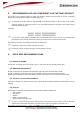
Figure 40: Power supply command by a GPIO
This kind of schematic could also be used to save few micro amperes in case of need. As the module has
a drain current of up to 56µA, this kind of function could lower it to the current through R4.
These, are the behaviours of the VGPIO and the CTS signal during the power off sequence.
Figure 41: Power OFF sequence for POK_IN, VGPIO and CTS
4.19 SLEEP MODE MANAGEMENT AND POWER CONSUMPTION
The AT command “AT+KSLEEP” allows to configure the sleep mode.
When AT+KSLEEP=1 is configured:
• The HiLoNC V2 module decides by itself when it enters in sleep mode (no more task running).
• “0x00” character on serial link wakes up the HiLoNC V2 module.
When AT+KSLEEP=0 is configured:
• The HiLoNC V2 module is active when DTR signal is active (low electrical level).
• When DTR is deactivated (high electrical level), the HiLoNC V2 module enters in sleep mode after a
while.
• On DTR activation (low electrical level), the HiLoNC V2 module wakes up.
When AT+KSLEEP=2 is configured:
• The HiLoNC V2 module never enters in sleep mode.
In sleep mode the module reduces its power consumption and remains waiting for the wake up signals either
from the network (i.e. Read paging block depending on the DRX value of the network) or the operating system
(i.e. timers wake up timers activated) or the host controller (i.e. character on serial link or DTR signal).The
power consumption should look like the following example for DRX9.
POK_IN Internal
pull up to 3V
*Must be High
VGPIO
Module is ON
Module is
OFF
Typ 2 seconds
AT*PSCPOF
CTS