
User's Manual


page 37/64
Note d’étude / Technical document : URD1– OTL
5665.3
– 003 / 72238 Edition 01
Document Sagemcom Reproduction et divulgation interdites
Sagemcom document. Reproduction and disclosure prohibited
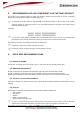
4.16 POWER ON AND SLEEP DIAGRAMS
Those 2 diagrams show the behaviours of the module and the DTE during the power on and then in the sleep
modes.
Figure 37: Diagram for the power on
DTE is in idle mode
VGPIO rise to 2.8V
U.A.R.T.
closed ?
VBAT≥3.2
Volts min
stable?
POK_IN
LOW for 2s
AND Reset
High?
CTS is Low and /or
KSUP
notified if KSREP
activated
Module is ready
to receive and
send AT