
User's Manual


page 33/64
Note d’étude / Technical document : URD1– OTL
5665.3
– 003 / 72238 Edition 01
Document Sagemcom Reproduction et divulgation interdites
Sagemcom document. Reproduction and disclosure prohibited
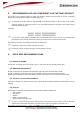
If a straight connection is used between the HiLoNC V2 and the DTE UART it is necessary to isolate host
and HiLoNC V2 module in order to avoid generating current re-injection through when HiLoNC V2 is switched-
off.
Example of schematic (only useful signals are represented):
Figure 33: Hardware interface diodes solution between HiLoNC V2 and host
Figure 34: Hardware interface buffers solution between HiLoNC V2 and host
4.14.5 ADVICES FOR EVERY POWER DOMAIN
• To avoid any current re-injection on VANA (2.85V)
If an external bias voltage over VANA is used for the microphone, use a 10µF serial capacitor to block the
DC voltage.
If a voltage higher than VANA has to be measured by the ADC, use external resistor divider to limit it.
if PWM bus is output only, the external system is supposed to be in input on the same voltage domain, if it is
not the case or if its inputs are pulled up and able to source current while the module is off, then simply use
open drain or open collector transistors to avoid any flow back current to the module.
The external system connected to the module by the UART has to switch its UART lines off while the module
is off. If the external system cannot commands its UART lines off, then it is necessary to add a buffer between
the module and the external system to prevent any issue. In this last case, the buffer would have to be enabled
by the VGPIO voltage that is only available when the module starts. This applies to TXD, RXD, RTS, CTS which
are on this power domain and also to the lines on the VGPIO power domain (see here after).
• To avoid any current re-injection on VGPIO (2.80V)
Do not connect a power supply to the VGPIO pad. This pad is an LDO output only.
The reset signal is internally pulled up and can be connected to an open drain transistor.
The GPIOs have to be used in compliance of the power domain and when the module is off, the external
system has to shut off its GPIOs.
The SPI bus has to be not connected to the external system.
The JTAG bus has to be not connected to the external system.
The UART lines on this power domain (DCD, DTR, DSR, RI) have to follow the same rules as those on
VANA domain (TXD, RXD, RTS, CTS). See have above.
A resistor of 10KΩ has to be connected to the E11 (NTRST) pad and GND to pull down this I/0, preventing
any deadlock due to VGPIO current re-injection.
Tri state command
Buffer
Host
HiLoNC V2
DTR, RTS, RXD
DCD, DSR, CTS, TXD, RI
DTR, RTS, RXD
DCD, DSR, CTS, TXD, RI
HiLoNC V2
Host
VGPIO