
User's Manual


page 22/64
Note d’étude / Technical document : URD1– OTL
5665.3
– 003 / 72238 Edition 01
Document Sagemcom Reproduction et divulgation interdites
Sagemcom document. Reproduction and disclosure prohibited
Avoid supplying the UART before the HiLoNC V2 module is ON, this could result in bad power up
sequence.
4.7.3 Complete V24 interface with PC
It supports speeds up to 115.2 Kbps and may be used in auto bauding mode.
To use the V24 interface, some adaptation components are necessary to convert the +2.8V signals from the
HiLoNC V2 to +/- 5V signals compatible with a PC.
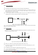
Figure 20: connection to a data cable
Avoid supplying the UART before the HiLoNC V2 module is ON, this could result in bad power up
sequence. To have a proper behaviour use the signal VGPIO to enable the RS232 Transceiver.
To create your own data cable (for software download purpose…etc…) refer to the following schematic as an
example with a MAX3238E:
• VCC_3V1 is an LDO output (VBAT to VCC_3V1) enabled by VGPIO from the module.
• 180Ω are serial resistors aimed to limit the EMC and ESD propagation.
RXD
CTS
DSR
DCD
RI
DTR
TXD
RTS
HiLoNC V2 Module
TXD
CTS
DSR
DCD
RI
DTR
RXD
RTS
RS232 Transceiver
IN
IN
IN
IN
IN
OUT
OUT
OUT
OUT
OUT
OUT
OUT
OUT
IN
IN
IN
DCE point of view
DTE point of view
SUBD9 Female
Note: pin 5 is GND
1
6
9
5
2
8
6
1
9
4
3
7
2.8V signals
3.1V to +/-5.5V
signals
39
40
33
34
35
36
38
37