
User's Manual


page 21/64
Note d’étude / Technical document : URD1– OTL
5665.3
– 003 / 72238 Edition 01
Document Sagemcom Reproduction et divulgation interdites
Sagemcom document. Reproduction and disclosure prohibited
Consult the AT command Specification document for the use of the UART signals.
Unused signals can be left not connected.
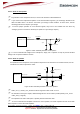
4.7.2 Complete V24 – connection HiLoNC V2 - host
A V24 interface is provided on the 51 pads of the HiLoNC V2 module with the following signals: RTS/CTS,
RXD/TXD, DSR, DTR, DCD, RI.
The use of this complete V24 connection is recommended as soon as your application needs to exchange
data (over GPRS or CSD).
Figure 18: Complete V24 connection between HiLoNC V2 and host
This configuration allows to use the flow control RTS & CTS to avoid any overflow error during the data transfer,
CTS is moreover used to signal when the HiLoNC V2 is ready to receive an AT command after a power up
sequence or a wake up from sleep mode.
This configuration allows as well all the signalling signals like:
• RI signal used when programmed to indicate an incoming voice or data call or SMS incoming etc…
• DCD signal used to signal the GPRS connections
• DSR signal used to signal the module UART interface is ON
• DTR signal used to prevent the HiLoNC V2 module from entering into sleep mode or to switch between
Data and AT commands or to hang up a call or to wake up the module etc…
Figure 19: CTS versus POK_IN signal during the power on sequence.
DCE point of view
DTE point of view
RXD
CTS
DSR
DCD
RI
DTR
TXD
RTS
HiLoNC V2 Module
TXD
CTS
DSR
DCD
RI
DTR
RXD
RTS
DTE Device
2.8V signals
39
40
33
34
35
36
38
37
2.8V signals
Note: GND is not
represented