
User's Manual


page 20/64
Note d’étude / Technical document : URD1– OTL
5665.3
– 003 / 72238 Edition 01
Document Sagemcom Reproduction et divulgation interdites
Sagemcom document. Reproduction and disclosure prohibited
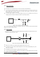
4.6.3 Simple 4V boost converter.
Simple boost converter with Linear LT1913 (see LT1316 evaluation kit document). The input can be preceded
by an AC/DC converter to get the 5V. PGOOD signal can be checked before the ignition of the module.
Figure 17: Example with Linear LT1913
4.7 UART
The HiLoNC V2 module features a V24 interface to communicate with the host through AT commands or for
easy firmware upgrading purpose.
It is recommended to manage an external access to the V24 interface, in order to allow easy software
upgrade (baud rate up to 460.8kbps, validated with ATEN USB/Serial converter).
DTR, DSR, DCD and RI signals are internally pull upped to VGPIO with a 100KΩ.
RI signal is a stand alone signal that can be used with anyone of the following configurations. Consult the
AT command specification for more information about this signal and its use.
4.7.1 Signals reminder
The following table quickly sums up the use of the different signals from UART
Signal name Signal use(DTE point of view)
RX
Receive data
TX
Transmit data
DCD
Signal data connections in progress (GPRS or CSD)
DSR
Signal UART interface is ON
DTR
Prevent the HiLoNC V2 to enter into sleep mode
Switch between data and command modes
Wake up the module,…
RTS
Wakes up the module when Ksleep=1 is used
CTS
Signal HiLoNC V2 is ready to receive AT commands, has waken
up
RI
Signal incoming calls (voice and data), SMS,…