
User's Manual


page 14/64
Note d’étude / Technical document : URD1– OTL
5665.3
– 003 / 72238 Edition 01
Document Sagemcom Reproduction et divulgation interdites
Sagemcom document. Reproduction and disclosure prohibited
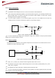
4.2.1.1 Notes for microphone
Pay attention to the microphone device, it must not be sensitive to RF disturbances.
If you need to have deported microphone out of the board with long wires, you should pay attention to the
EMC and ESD effect. It is also the case when your design is ESD sensitive. In those cases, add the
following protections to improve your design.
To ensure proper operation of such sensitive signals, they have to be isolated from the others by
analogue ground on customer’s board layout. (Refer to Layout design chapter)
Figure 8 : Filter and ESD protection of microphone
To use an external bias voltage for the microphone, simply use a capacitor of 10µF to prevent this bias
voltage to be re-injected inside the module.
4.2.1.2 Notes for speaker
As explained for the microphone, if the speaker is deported out of the board or is sensitive to ESD, use the
schematic here after to improve the audio.
Figure 9: Filter and ESD protection of 32 ohms speaker
HSET_OUT_P, HSET_OUT_N tracks must be larger than other tracks: 0.1 mm.
As described in the layout chapter, differential signals have to be routed in parallel (HSET_OUT_P and
HSET_OUT_N signals)
The impedance of audio chain (filter + speaker) must be lower than 32Ω.
To use an external audio amplifier connected to a loud-speaker, use serial capacitors of 10nF on HiLoNC
audio outputs to connect the audio amplifier.
HiLoNC V2
INTMIC_P
MIC
Ferrite Bead
18pF
ESD protection
HiLoNC V2
HSET_OUT_P
HSET_OUT_N
speaker
Ferrite Bead
Ferrite Bead
18pF
18pF
ESD protection
ESD protection