
User's Manual


page 18/35
Note d’étude / Technical document : URD1– OTL 5665.1– 002 / 70 884 Edition 03
Document Sagem Communications Reproduction et divulgation interdites
Sagem Communications document. Reproduction and disclosure prohibited
Figure 14: Example of a connection to a data cable
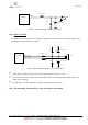
3.6.3 Partial V24 (RX-TX-RTS-CTS) – connection HiloNC - host
When using only RX/TX/RTS/CTS instead of the complete V24 link, we recommend following schematic.
Figure 15: Partial V24 connection (4 wires) between HiloNC and host
As we need DTR active (low electrical level), a loop DSR on DTR is sufficient because DSR is active (low
electrical level) once the HiloNC is switched on.
DCD and RI can stay not connected and floating.
RXD
CTS
DSR
DCD
RI
DTR
TXD
RTS
HiLoNC Module
TXD
CTS
DSR
DCD
RI
DTR
RXD
RTS
DTE Device
2.8V signals
39
40
33
34
35
36
38
37
2.8V signals
Note: GND is not
represented