
User's Manual


page 17/35
Note d’étude / Technical document : URD1– OTL 5665.1– 002 / 70 884 Edition 03
Document Sagem Communications Reproduction et divulgation interdites
Sagem Communications document. Reproduction and disclosure prohibited
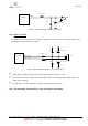
Figure 12: Complete V24 connection between HiloNC and host
3.6.2 Complete V24 interface with PC
It supports speeds up to 115.2 Kbps and may be used in auto bauding mode.
To use the V24 interface, some adaptation components are necessary to convert the +2.8V signals from the
HiloNC to +/- 5V signals compatible with a PC.
Figure 13: connection to a data cable
To create your own data cable (for software download purpose…etc…) please refer to the following schematic
as an example:
DCE point of view DTE point of view
RXD
CTS
DSR
DCD
RI
DTR
TXD
RTS
HiLoNC Module
TXD
CTS
DSR
DCD
RI
DTR
RXD
RTS
DTE Device
2.8V signals
39
40
33
34
35
36
38
37
2.8V signals
Note: GND is not
represented
RXD
CTS
DSR
DCD
RI
DTR
TXD
RTS
HiLoNC Module
TXD
CTS
DSR
DCD
RI
DTR
RXD
RTS
RS232 Transceiver
IN
IN
IN
IN
IN
OUT
OUT
OUT
OUT
OUT
OUT
OUT
OUT
IN
IN
IN
DCE point of view DTE point of view
SUBD9 Female
Note: pin 5 is GND
1
6
9
5
2
8
6
1
9
4
3
7
2.8V signals
3.1V to +/-5.5V
signals
39
40
33
34
35
36
38
37