
User's Manual

1
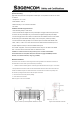
Important Information about the Sagemcom F@ST 2705 WS:
Operational working:
F@ST2705 WS must be used in a temperature controlled place. It is compliant to ETS 300 019-1-3 Class T
3.2 standard:
1.
Temperature : 0°C to +45°C
2. Solar Radiation : 700w / m
3. Relative humidity : 5 to 85 % without condensation
4. No Airflow
Installation and Safe Usage Instructions:
1. Place the ADSL gateway on a flat surface.
2.
Connect the manufacturer supplied AC to DC power adapter. The F@ST 2705 router requires the use
of a 12VDC, 500 mA power adapter. Only use a manufacturer supplied and approved power adapter.
3. Connect the F@ST 2705 to the AC Mains in accordance with the installation instructions in this booklet,
and the markings on the identification label (voltage, current, and frequency of electricity network).
4. Connect the Ethernet cable (provided) to one of the RJ45 ports on the ADSL Router labeled "LAN1",
"LAN2", "LAN3", or "LAN4". Then connect the other end of the Ethernet Cable to the Ethernet port of a
computer. Repeat as necessary for the other available Ethernet ports.
5. For a ADSL configuration, connect the provided DSL Cable to the port on the ADSL Router labeled
"DSL". Connect the other end of the DSL Cable to a standard Phone Jack.
CAUTION: To reduce the risk of fire, always and only use a UL Listed or CSA Certified
Telecommunication Line Cord (DSL cable) with a minimum wire gauge of 26AWG (0.4 mm dia.
minimum, or 0.129 mm² minimum) or larger (e.g., 24AWG).
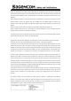
Wall Mount Installation
This device can be mounted on a wall using the two mounting brackets on the bottom of the device,it is
recommended to use two round or pan head screws (not included)
1. Install two screws horizontally apart on a wall using the measurement shown in Figure 1. The screws
should protrude from the wall in order to fit the device between the head of the screw and the wall. If the
screws are installed in drywall. Use hollow wall anchors to ensure that the unit does not pull away from
the wall due to prolonged strain from the cable and power connectors.
2. Remove the device from the product package.
3. Mount the device on the wall.
Refer to Figures 1 and 2 for more details.
Figure 1: Distance (horizontal) Between Brackets for Screws Figure 2: Recommended Screw Size