
Technical information

Proc Sheet 1 02
MyX-4
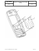
REMOVING / REPLACING THE DISPLAY
1/2
Ref. SCT U33 SM DTS 004– Index A - 29/03/01 Page 5-20
Tools :
- A 0.6mm torx screwdriver
- gloves
- Display / metal dome jig
Notice:This procedure must be performed by an technician provided with gloves , to avoid any risk
of pollution.
• Display contacts must never be touched.
Preliminary operation
1. Remove the back cover ( Proc sheet 0 01).
2. Remove the battery ( Proc sheet 0 02).
3. Remove the front cover ( Proc sheet 0 03).
4. Remove the assembly flange ( Proc sheet 1 01).
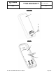
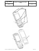
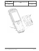
Removal procedure :
1. Turn the display round (2) to the right of the electronic board (1)
2. Push on the flex PCB (3) to liberate the display board to board connector
3. Remove the display (2)
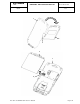
Placement procedure :
1. Position the display (2) in its housing first
2. Position the display board to board connector on the electronic board connector (4) and press into
locked position
Further operations :
1. Remove the assembly flange ( Proc sheet 1 01).
2. Replace the front cover (Proc sheet 0 03).
3. Replace the battery (Proc sheet 0 02).
4. Replace the back cover (Proc sheet 0 01).
1. Carry out the radio test (Test Sheet 06).
.