
Technical information


Proc sheet 2 02
myC2-3
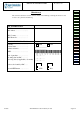
5HPRYHDQGSODFHKSYLEUDWRU
)3&/&'IODS
1/1
7RROV
-Tweezers
- Iron has to weld
3UpOLPLQDLUHRSHUDWLRQ
1. Remove the battery (Proc sheet 0 01).
2. Remove the lower housing of mobile (Proc sheet 1 01).
3. Remove the keyboard (Proc sheet 1 04))
4. Remove MMI board (Proc sheet 1 07).
5. Remove the flap (Proc sheet 1 09).
6. Remove housing Flap (Proc sheet 1 10).
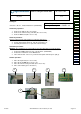
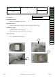
5HPRYDOSURFHGXUH
1. Unsolder the 2 threads of the HP ( 1 ), then extract the HP ( 3 ).
2. Unsolder the 2 threads of the vibreur (2), then extract the vibrator (4).
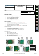
3. Disassemble ciu/lcd of upper housing flap.
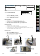
4. Unsolder the FPC, Disconnect of connect BTB.(5), To extract the FPC.
3ODFHPHQWSURFHGXUH
1. Position the FPC. Solder Mass plan (6).
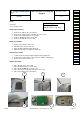
2. Position the vibrator. Solder the 2 threads (red and black) (7).
3. Position the HP. Solder the 2 threads (white and black) (7).
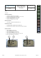
)XUWKHURSHUDWLRQV
1. Place the flap (Proc sheet 1 09)
2. Place the keyboard ( Proc sheet 1 04).
3. Place the board MMI (Proc sheet 1 07).
4. Place the lower housing of mobile (Proc sheet 1 01).
5. Place of the battery (Proc sheet 0 01)
Risk of the procedure :
Damage LCD, FPC, Hp, vibreur
Thread red vibreur
Thread black vibreur
Thread black Hp
Thread white Hp
Procedure
Proc 0 01
Proc 1 01
Proc 1 02
Proc 1 03
Proc 1 04
Proc 1 05
Proc 1 06
Proc 1 07
Proc 1 08
Proc 1 09
Proc 1 10
Proc 1 11
Proc 1 12
Proc 2 02
Proc 3 01
Proc 3 02
Proc 4 01
Symptom
Symp 01
Symp 02
Symp 03
Symp 04
Symp 05
Symp 06
Symp 07
Symp 08
Symp 10
Test
Test 01
Test 02
Test 03
Test 04
Test 05
Test 06
Contents REF MTB DTS 8- Indice B - February 21 2006 Page 5-21