
Technical information


Proc Sheet 2 03
myC3-2
5HPRYHDQG3ODFHWKHVLGHNH\SDG
1/1
7KLVRSHUDWLRQPXVWEHPDGHDIWHUOLFHQVH6$*(0
7RROV
- Soldering iron
- Plait to be unsoldered
- Tools for positioning the side keypad
3UHOLPLQDU\RSHUDWLRQ
1. Remove the battery ( Proc Sheet 0 01 ).
2. Remove the lower casing of mobile ( Proc Sheet 1 01 ).
3. Remove the volume control key ( Proc Sheet 1 02 ).
4. Remove the micro rubber ( Proc Sheet 1 06 ).
5. Remove the equipped electronic board ( MMI II ) ( Proc Sheet 1 10 ).
5HPRYDOSURFHGXUH
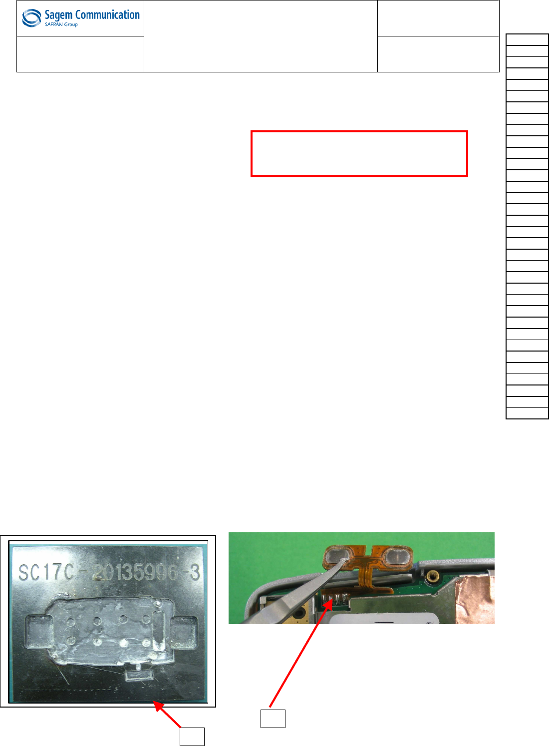
1. Positionner la MMI II sur le posage (1) et dessouder la touche latérale (2).
3ODFHPHQWSURFHGXUH
1. Positionner la MMI II sur le posage (1) et souder la touche latérale (2)..
)XUWKHURSHUDWLRQV
1. Place the equipped electronic board ( MMI II ) ( Proc Sheet 1 10 ).
2. Place the micro rubber ( Proc Sheet 1 06 ).
3. Place the volume control key ( Proc Sheet 1 02 ).
4. Place the lower casing of mobile ( Proc Sheet 1 01 ).
5. Place the battery ( Proc Sheet 0 01 ).
2
1
Risk of the procedure :
• Damage the FPC of the side
keypad.
Procedure
Proc 0 01
Proc 1 01
Proc 1 02
Proc 1 03
Proc 1 04
Proc 1 05
Proc 1 08
Proc 1 10
Proc 1 18
Proc 1 20
Proc 1 22
Proc 2 01
Proc 2 03
Proc 3 01
Proc 3 02
Proc 4 01
Symptom
Symp 01
Symp 02
Symp 03
Symp 04
Symp 05
Symp 06
Symp 07
Symp 08
Symp 10
Test
Test 01
Test 02
Test 03
Test 04
Test 05
Test 06
Contents REF MTB DTS 1- Indice D - November 10 2005 Page 5-25