
Technical information


Proc Sheet 1 08
myC3-2
5HPRYHDQG3ODFHWKHPHWDOGRPH
1/2
7RROV
- Tweezers
- Soldering iron
- Gloves
- Fixture for metal Dome
3UHOLPLQDU\RSHUDWLRQ
1. Remove the battery ( Proc Sheet 0 01 ).
2. Remove the lower casing of mobile ( Proc Sheet 1 01 ).
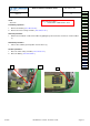
5HPRYDOSURFHGXUH
This procedure must be performed by a technician with gloves.
1. Apply the operation of the Proc Sheet 1 02.
2. Unstick (1) by means of the tweezers the side key.
3. Take off by means of tweezers (5) the ESD copper (6).
4. Remouve the MMI II (7) from the upper casing of mobile by levering the clip (8).
5. Catch hold of the metal dome (9) paying attention not to break the component.
3ODFHPHQWSURFHGXUH
:DUQLQJ7KHPHWDOGRPHLVQRWUHXVDEOH LWPXVWEHUHSODFHGE\DQHZPHWDOGRPHXQOHVVWKH
ERDUGLVVZDSSHGDQGVHQWDVOHYHO
1. Unsolder the FPC LCD (10) and remove the FPC LCD connector from the ZIF connector (11).
2. Stick a new metal dome (12) on the electronic card (7) using placing tool and watching not to put fingers
on the small metal dishes.
3. Unsolder the FPC LCD (10) and put the FPC LCD on the ZIF connector (11).
4. Close the connector ZIF.
5. Put the MMI II (7) in its slot.
6. Restick (1) by means of tweezers the side keypad.
7. Apply the operations of the Proc Sheet 1 02.
)XUWKHURSHUDWLRQV
1. Place the lower casing of mobile ( Proc Sheet 1 01 ).
2. Place the battery ( Proc Sheet 0 01 ).
Risk of the procedure :
• Damage the FPC connector.
• Damage the volume control key.
• Damage the components of MMI II.
Procedure
Proc 0 01
Proc 1 01
Proc 1 02
Proc 1 03
Proc 1 04
Proc 1 05
Proc 1 08
Proc 1 10
Proc 1 18
Proc 1 20
Proc 1 22
Proc 2 01
Proc 2 03
Proc 3 01
Proc 3 02
Proc 4 01
Symptom
Symp 01
Symp 02
Symp 03
Symp 04
Symp 05
Symp 06
Symp 07
Symp 08
Symp 10
Test
Test 01
Test 02
Test 03
Test 04
Test 05
Test 06
Contents REF MTB DTS 1- Indice D - November 10 2005 Page 5-13