
Technical information


Site technical documentation myc3-2,myc3-2j
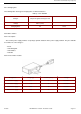
2.3 IN & OUT CONNECTOR
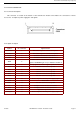
2.3.1 Connector description
This connector is located at the bottom of the transmission module and enables the connection to various
accessories. It comprises power supply pins and signals.
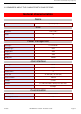
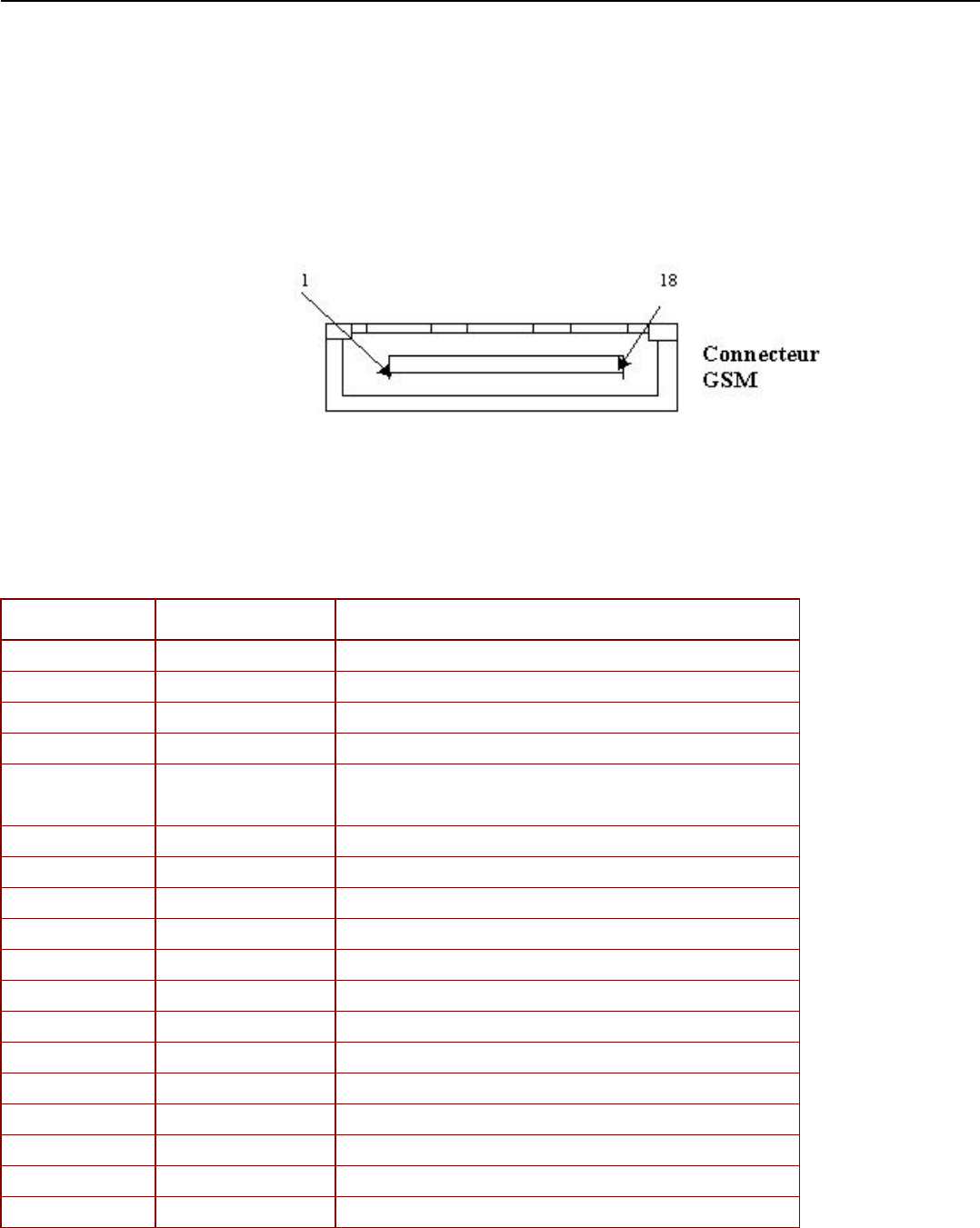
2.3.2 Signal description
Symbol Pin connector Signal fonction
HSCMICIP 1 Differential inpout for external microphone
HSCMICN 2 Differential inpout for external microphone
HSOL 3 STEREO AND MONO AUDIO OUTPUT
HSOR 4 STEREO AND MONO AUDIO OUTPUT
VBAT 5
POWER SUPPLY IMAGE VOLTAGE, connect this
signal to "CHARGER" (pin n°1) to switch the module on.
INTI2C 6 Interrupt signal reserved for sagem specific accessories
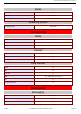
CTS 7 Link v24 suit for accessory data
RTS 8 Link v24 suit for accessory data
DSR 9 Link v24 suit for accessory data
DTR 10 Link v24 suit for accessory data
TXD1 11 Link V24 suit for accessory data
Chargeur 12 Phone set power ON and power supply signal
GND 13 ZERO VOLT
RXD1 14 Link V24 suit for accessory data
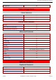
R1 15 Complete V24 tie for data accessories
DCD 16 Complete V24 tie for data accessories
RXD2 17 Application input serial n°2
Chargeur 18 Phone set power ON and power supply signal
Contents REF MTB DTS 1- Indice D - November 10 2005 Page 2-7