SITE TECHNICAL DOCUMENTATION myc3-2,myc3-2j Doc. No.
Site technical documentation myc3-2,myc3-2j Contents REF MTB DTS 1- Indice D - November 10 2005 Page 2
Site technical documentation myc3-2,myc3-2j CONFIDENTIALITY This document is SAGEM's limited company property. It can not be reproduced or communicated without the written license.
Site technical documentation myc3-2,myc3-2j Contents CHAPTER 1 - FOREWORD 1-1 HOW TO USE THE SITE TECHNICAL DOCUMENTATION 1-1-1 Use 1-2 ABREVIATIONS 1-3 COMMENTS SHEET CHAPTER 2 - DESCRIPTION - OPERATION 2-1 REMINDERS ABOUT THE GENERAL CHARACTERISTICS OF GSM AND PCS NETWORKS 2-2 REMINDERS ABOUT THE HAND SET CHARACTERISTICS 2-3 IN & OUT CONNECTOR 2-3-1 Connector description 2-3-2 Signal description 2-4 IDENTIFICATION 2-4-1 Illustration 2-4-2 Description 2-4-3 Description after reparation 2-5 PHONE BLOCK DI
Site technical documentation myc3-2,myc3-2j TEST SHEETS CHAPTER 5 - MAINTENANCE PROCEDURES 5-1 TECHNICAL WORK LEVELS 5-2 SHORT LOOP PROCESS 5-3 MAINTENANCE TOOLS PROCEDURE SHEETS CHAPTER 6 - ACCESSORIES 6-1 CIGAR LIGHTER CHARGERAC1 6-1-1 Description 6-1-2 Charactéristics 6-2 PEDESTRIAN HANDSFREE KIT 6-2-1 Description 6-2-2 Charactéristics 6-3 DATA CABLE PC USB 6-3-1 Description 6-3-2 Charactéristics CHAPTER 7 - TECHNICAL INFORMATION BULLETIN 7-1 PURPOSE 7-2 APPLICATION CHAPTER 8 - ILLUSTRATED PARTS CATAL
Site technical documentation myc3-2,myc3-2j CHAPTER 1 - FOREWORD This document is common to all myc3-2,myc3-2j phones in the SAGEM. It is composed of independent sheets: -Symptom sheets = Symp Sheet XX -Test and check sheet= Test Sheet XX -Maintenance procedure sheet= Proc Sheet X XX The applicability of a procedure is indicated in the independent sheets title block. These sheets are updated from time to time in Technical Information Bulletins (TIB).
Site technical documentation myc3-2,myc3-2j Chapter 2: Description - Operation, describes general data and options available in the myc3-2,myc3-2j. Chapter 3: Symptoms, contains troubleshooting procedures to be carried out on equipment. Chapter 4: Tests and checks, contains tests and check procedures to be performed on the equipment. Chapter 5: Maintenance procedures, contains level 0 to 2 maintenance procedures to be carried out on the equipment, and the procedure to return to SAGEM level 3.
Site technical documentation myc3-2,myc3-2j PIN Personal Identity Number PUK PIN Unlocking key RF Radio Frequence SAR Specific Absortion Rate SIM Subscriber Identity Module SMS Short Message Service SMS CB Short Message Service Cell Broadcast SMT Sagem Mobile Tools TFT Thin Film Transistor USSD Unstructured Supplementary Service Data VGA Video Graphics Array WAP Wireless Application Protocol WiFi Wireless Fidelity WSP Wireless Session Protocol 1.
Site technical documentation myc3-2,myc3-2j Document title: 6LWH 7HFKQLFDO 'RFXPHQW Reference : Date : Please fill in the following table : ([FHOOHQW *RRG )DLUO\ JRRG 3DVVDEOH Easy to find the required information Clarity of information provided Quality and accuracy of information given Document outline Document presentation and appearance Quality of illustrations General satisfaction Do you think this document could be improved ? if so, how ? : Improve the overall view Improve the table of cont
Site technical documentation myc3-2,myc3-2j CHAPTER 2 - DESCRIPTION - OPERATION 2.
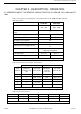
Site technical documentation myc3-2,myc3-2j 2.2 REMINDERS ABOUT THE CHARACTERISTICS AND OPTIONS General characteristics Name Name myc3-2,myc3-2j Size Dimensions 77x41.7x22.
Site technical documentation myc3-2,myc3-2j Radio Type GSM biband GSM Band 900/1800 mhz Voice codecs EFR, HR, FR, AMR Operating system Operating System Proprietary Connectivity Radio GPRS Yes class 10 (4+1 & 3+2) EDGE no UMTS no Internet Browser Wap 1.
Site technical documentation myc3-2,myc3-2j E mail no IMPS no Predictive text input T9 Video & images Camera no Image features no Video Player no Image Format BMP,WBMP,PNG,JPEG,GIF,GIF Audio Audio player yes Audio Recorder yes FM radio no Polyphonic ringtones Audio formats yes,16 tones IMELODY,MIDI,WAV (PCM, ADPCM), AMR Entertainement Wallpaper Yes ( 20 + hazardous choice) Screensaver Yes ( 2 animations + 20 wallpapers ) Clock display Yes, analog or digital Icons yes Bookmarks
Site technical documentation myc3-2,myc3-2j Java application No Call management Voice features Mute mode yes Numerotation vocale no Integrated handsfree mode yes Adress book features Call group yes Ringtone and Icone customisation yes Personal information management yes Advanced features Conference call yes Anonymus mode yes Call wait yes Call forwarding yes Automatic redial yes SIM toolkit yes Vibrate mode yes Speed dialing Voice mail box only (press on key 1) Call list yes
Site technical documentation myc3-2,myc3-2j Silent key Yes, by long press on # International access key Yes, by long press on 0 Menu key yes Personnal management features Calculator yes Alarm Clock yes Timer no Organizer yes To do yes Voice recorder Yes, codec AMR Currency converter yes Languages Up to 4 languages embedded Memory Memory Internal phone book Up to 255 Memoire message Up to 100 Redial List Up to 20 Additional multimedia memory Embedded memory Contents no Up to 28
Site technical documentation myc3-2,myc3-2j 2.3 IN & OUT CONNECTOR 2.3.1 Connector description This connector is located at the bottom of the transmission module and enables the connection to various accessories. It comprises power supply pins and signals. 2.3.
Site technical documentation myc3-2,myc3-2j 2.4 IDENTIFICATION All phones are identified with an identification label sticked on the antenna. 2.4.1 Illustration 2.4.2 Desrcription a1 : IMEI (bar code), a2 : IMEI (15 characters) b1 : Reference of product / aesthetic used . b2 : Kind of handset / SAGEM Family. c1: customer personalisation d1: Production date (date code) + Production level, Ex. F260/03 = (F) fabrication area (F : Fougères), (260) day of year, (03) last digit of year (03®2003).
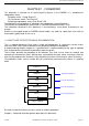
Site technical documentation myc3-2,myc3-2j - 260/03 -> Date of repair (260), repairing day (03), last digit of year (03->2003). 2.5 PHONE BLOCK DIAGRAM 2.5.1 block diagram 2.5.2Standards and environment The phone complies with the following standards. Directive EEC 1999 / 5 / CE Safety (security) EN 60950 CEM EN 301 489-1 / EN 301 489-7 Voltage 73 / 23 / EEC Network 3GPP TS 51.010-1 v 5.2.0 with included GCF-CC V 3.10.0 Requirements GT01 v 4.7.
Site technical documentation myc3-2,myc3-2j 2.6.1 Battery packs 2.6.1.1 Charactéristics Designation Technology Weight Voltage Capacity 2.6.1.2Description Li-ion type batteries are used. They are rechargeable using: - mains power supply module. Batteries caution use: ·Store the batteries in a dry and cool place (excessive cold and heat damage the batteries reliability). ·They must never be stored in bulk, even the rejects, to avoid any short circuits. ·Do not dismantle the battery packs.
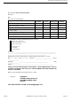
Site technical documentation myc3-2,myc3-2j 2.6.1.3Charging time The following table shows typical charging times for different batteries. Battery : Li-Ion 650mAh Charger simple unregulated chargers 230 Voltage 230 V (110V) Charging times 2h 1h 45 2.6.2 Mains modules 2.6.2.1 Description These mains power supply modules accept large dynamic variations in the power supply network. They are available for a number of connector types: - E.E.C, - United Kingdom - United States, - Australia. 2.6.2.
Site technical documentation myc3-2,myc3-2j 2.6.2.
Site technical documentation myc3-2,myc3-2j CHAPTER 3 - SYMPTOMS 3.1 GENERAL After you have received the customer return sheet (Proc Sheet 3 02), carry out the troubleshooting procedure. This chapter will help you to identify the defective element(s), using the troubleshooting table. It contains flow charts broken down by fault type. Each flow chart describes the procedure to be followed and contains cross references to tests or maintenance. These flow charts should be followed in full.
Site technical documentation myc3-2,myc3-2j Visual test Customer fault verification Default confirmed? No Yes Standard test Yes Software inspection - Update Default found ? No Repairing => symptom sheet Standard test No No Default > Level 2 ? Mobile OK? No Yes Yes Return to Sagem Contents > 1 return no found ? Yes Delivery to customer REF MTB DTS 1- Indice D - November 10 2005 Return to Sagem Page 3-2
Site technical documentation myc3-2,myc3-2j Visual test : -Connector condition (in / out connector, battery, SIM) -keypad concdition (elastomer,inscription) -Pane condition -Plug and position of battery -SIM card position -Oxidation -Charger test Standard test : -Display test : Hot Line menu -Contrast control -All keypad keys test (check bips keys) -Test fonction camera -Audio and radio test -Battery charge test -Vibrating device test : Hot Line menu Software inspection : For all mobiles to repair, the che
Site technical documentation myc3-2,myc3-2j 3.
Site technical documentation myc3-2,myc3-2j Proc sheet 1 20 B13 Intermittent cut with reboot Proc sheet 3 01 Intermittent cut without reboot Proc sheet 1 20 B14 Proc sheet 3 01 C1 Not functioning keyboard Symp sheet 05 C2 Lateral key problem Symp sheet 05 Proc sheet 1 20 D1 SIM missing Proc sheet 3 01 Proc sheet 1 20 D2 Other messages Proc sheet 3 01 Proc sheet 1 20 D3 EEPROM problem Proc sheet 3 01 Proc sheet 1 20 D4 Untuned mobile Proc sheet 3 01 Proc sheet 1 20 D5 Hard failure Proc she
Site technical documentation myc3-2,myc3-2j E4 Vibrating device malfunction Symp sheet 07 E5 Vibrating device malfunction Symp sheet 07 E6 Defective audio connector Symp sheet 08 F1 No network localisation Symp sheet 02 F2 Intermittent calls drop Symp sheet 02 F4 Radio control no OK Proc sheet 1 20 Proc sheet 3 01 F5 Outgoing call failure Symp sheet 02 F6 Incoming call failure Symp sheet 02 G1 Broken or damaged window Proc sheet 1 10 G2 Broken or damaged cover Proc sheet 1 10 G
Site technical documentation myc3-2,myc3-2j 3.
Site technical documentation myc3-2,myc3-2j K.PAD LOCKED PRESS *OK Keypad locked Menu not available for this OPTION NOT AVAILABLE product version PROG.
Site technical documentation myc3-2,myc3-2j 3.5 LIST OF OBSERVED DEFECTS A SAGEM code is assigned to each confirmed defect. This code should be entered on Proc Sheet 3 01, SAGEM Factory Return, if the phone to be repaired is returned to SAGEM (see chapter 5). 3.
Site technical documentation myc3-2,myc3-2j SYMPTOM SHEETS Contents REF MTB DTS 1- Indice D - November 10 2005 Page 3-10
ENDURANCE BATTERY SYMP SHEET 01 AND CHARGER PROBLEM myc3-2,myc3-2j 1/1 Test the charger 7HVW 6KHHW No Replace the charger Ok ? yes Test the consumption 7HVW 6KHHW No Return to SAV )LFKH 3URF RX 3URF Ok ? yes Symptom Symp 01 Symp 02 Symp 03 Symp 04 Symp 05 Symp 06 Symp 07 Symp 08 Symp 10 Procédure Proc 0 01 Proc 1 01 Proc 1 02 Proc 1 03 Proc 1 04 Proc 1 05 Proc 1 08 Proc 1 10 Proc 1 18 Proc 1 20 Proc 1 22 Proc 2 01 Proc 2 03 Proc 3 01 Proc 3 02 Proc 4 01 Test Test 01 Test 02
COMMUNICATION SYMP SHEET 02 PROBLEM myc3-2,myc3-2j 1/1 Realise the WAVETEK test 7HVW 6KHHW No Radio problem ? Non Yes Return to SAV 3URF 6KHHW RX 3URF Contents REF MTB DTS 1- Indice D - November 10 2005 end Symptom Symp 01 Symp 02 Symp 03 Symp 04 Symp 05 Symp 06 Symp 07 Symp 08 Symp 10 Procédure Proc 0 01 Proc 1 01 Proc 1 02 Proc 1 03 Proc 1 04 Proc 1 05 Proc 1 08 Proc 1 10 Proc 1 18 Proc 1 20 Proc 1 22 Proc 2 01 Proc 2 03 Proc 3 01 Proc 3 02 Proc 4 01 Test Test 01 Test 02 Test 03
NO FAULT GIVEN SYMP SHEET 03 Complete function by SMT myc3-2,myc3-2j 1/1 7HVW 6KHHW Test the charger 7HVW 6KHHW Found defect ? Yes No Test the Battery End 7HVW 6KHHW Found defect ? Yes No Test the consumption End 7HVW 6KHHW Found defect ? Yes No Test the display( menu HOTLINE) End 7HVW 6KHHW Found defect ? Symptom Symp 01 Symp 02 Symp 03 Symp 04 Symp 05 Symp 06 Symp 07 Symp 08 Symp 10 Procédure Proc 0 01 Proc 1 01 Proc 1 02 Proc 1 03 Proc 1 04 Proc 1 05 Proc 1
DISPLAY PROBLEM myc3-2,myc3-2j SYMP SHEET 04 1/1 Test the display with the Hot Line menu Black/color screen 7HVW 6KHHW yes Ok ? No end Change the display 3URF 6KHHW RU Test the display with the Hot Line menu 7HVW 6KHHW yes Ok ? Symptom Symp 01 Symp 02 Symp 03 Symp 04 Symp 05 Symp 06 Symp 07 Symp 08 Symp 10 Procédure Proc 0 01 Proc 1 01 Proc 1 02 Proc 1 03 Proc 1 04 Proc 1 05 Proc 1 08 Proc 1 10 Proc 1 18 Proc 1 20 Proc 1 22 Proc 2 01 Proc 2 03 Proc 3 01 Proc 3 02 Proc 4 01 Test Test
KEYPAD PROBLEM SYMP SHEET 05 myc3-2,myc3-2j 1/1 Activate the « Bip touch » function Test the keypad listening the « BIP touch yes Ok ? No end Change the dome métal 3URF 6KHHW RU RU RU Retest the keypad Symptom Symp 01 Symp 02 Symp 03 Symp 04 Symp 05 Symp 06 Symp 07 Symp 08 Symp 10 Procédure Proc 0 01 Proc 1 01 Proc 1 02 Proc 1 03 Proc 1 04 Proc 1 05 Proc 1 08 Proc 1 10 Proc 1 18 Proc 1 20 Proc 1 22 Proc 2 01 Proc 2 03 Proc 3 01 Proc 3 02 Proc 4 01 Test Test 01 Test 02 Test 03 T
RING TONES PROBLEM SYMP SHEET 06 myc3-2,myc3-2j 1/1 Select a ringtone in the Menu 6HWWLQJ VRXQGV ULQJWRQHV FDOO yes Ringtone Ok ? end No Change the speaker 3URF 6KHHW yes Ringtone Ok ? No Return to SAGEM )LFKH 3URF RX 3URF Contents REF MTB DTS 1- Indice D - November 10 2005 end Symptom Symp 01 Symp 02 Symp 03 Symp 04 Symp 05 Symp 06 Symp 07 Symp 08 Symp 10 Procédure Proc 0 01 Proc 1 01 Proc 1 02 Proc 1 03 Proc 1 04 Proc 1 05 Proc 1 08 Proc 1 10 Proc 1 18 Proc 1 20 Proc 1 22
VIBRATING DEVICE SYMP SHEET 07 PROBLEM myc3-2,myc3-2j 1/1 Test the vibrating device With the HOT LINE 7HVW 6KHHW yes Ok ? No end Change the vibrating device 3URF 6KHHW RU Test the vibrating device With the HOT LINE menu 7HVW 6KHHW Symptom Symp 01 Symp 02 Symp 03 Symp 04 Symp 05 Symp 06 Symp 07 Symp 08 Symp 10 Procédure Proc 0 01 Proc 1 01 Proc 1 02 Proc 1 03 Proc 1 04 Proc 1 05 Proc 1 08 Proc 1 10 Proc 1 18 Proc 1 20 Proc 1 22 Proc 2 01 Proc 2 03 Proc 3 01 Proc 3 02 Proc 4 01 Tes
AUDIO PROBLEM myc3-2,myc3-2j SYMP SHEET 08 1/1 Realise a Wavetek Test 7HVW 6KHHW No Audio problem? yes Replace the microphone And / or the speaker 3URF 6KHHW 3URF end Realise a Wavetek Test 7HVW 6KHHW Symptom Symp 01 Symp 02 Symp 03 Symp 04 Symp 05 Symp 06 Symp 07 Symp 08 Symp 10 Procédure Proc 0 01 Proc 1 01 Proc 1 02 Proc 1 03 Proc 1 04 Proc 1 05 Proc 1 08 Proc 1 10 Proc 1 18 Proc 1 20 Proc 1 22 Proc 2 01 Proc 2 03 Proc 3 01 Proc 3 02 Proc 4 01 Test Test 01 Test 02 Test 03 Te
LOUDSPEAKER PROBLEM myc3-2,myc3-2j SYMP SHEET 10 1/1 Do the wavetek Test 7HVW 6KHHW Replace the loudspeaker 352& 6+((7 RU Symptom Symp 01 Symp 02 Symp 03 Symp 04 Symp 05 Symp 06 Symp 07 Symp 08 Symp 10 Procédure Proc 0 01 Proc 1 01 Proc 1 02 Proc 1 03 Proc 1 04 Proc 1 05 Proc 1 08 Proc 1 10 Proc 1 18 Proc 1 20 Proc 1 22 Proc 2 01 Proc 2 03 Proc 3 01 Proc 3 02 Proc 4 01 Test Test 01 Test 02 Test 03 Test 04 Test 05 Test 06 Do the Wavetek test 7(67 6+((7 Return to SAGEM SAGEM SAV 352&
Site technical documentation myc3-2,myc3-2j CHAPTER 4 - TESTS AND CHECKS 4.1 ABOUT TESTS Tests and checks are made after the troubleshooting procedures (chapter 3) and before the maintenance procedures (chapter 5). They are broken down into modules and are sorted by types of confirmed faults. The user must be equipped with special test tools in order to carry out the tests. 4.2 TEST TOOLS The references of SAGEM tools, listed hereafter, are given in Appendix 1 : Composition table.
Site technical documentation myc3-2,myc3-2j 4.3.2 Installing the ARC downloading kit The ARC downloading kit interfaces the SMT software with the phone to be repaired. -Connect the 9-pin SUB-D connector to the PC serial port (COM1). -Connect the power supply module to the mains power outlet. -Connect the phone to be repaired to the system connector. 4.3.3 SMT functions The SMT maintenance software can: -Download new software if needed -Configure default values and checks them.
Site technical documentation myc3-2,myc3-2j TEST SHEETS Contents REF MTB DTS 1- Indice D - November 10 2005 Page 4-3
TEST AND CHECK BY SMT TEST SHEET 01 myc3-2,myc3-2j 1/7 ! " # $ % ! " ( 1 # 2 ) $ #)*+,- . /-,)#0 &/ 3 4 5 # #)*+,- & %' ' % . ,- -! - # 6 !7- .
TEST AND CHECK BY SMT TEST SHEET 01 myc3-2,myc3-2j 2/7 !" # 3 3 = % = 3 = 3 % % % " 3 > % 3 ?, 3 3 3 > ? 3 > $ ) -) 0 , % % Test Test 01 Test 02 Test 03 Test 04 Test 05 Test 06 Procedure Proc 0 01 Proc 1 01 Proc 1 02 Proc 1 03 Proc 1 04 Proc 1 05 Proc 1 08 Proc 1 10 Proc 1 18 Proc 1 20 Proc 1 22 Proc 2 01 Proc 2 03 Proc 3 01 Proc 3 02 Proc 4 01 Symptom Symp 01 Symp 02 Symp 03 Symp 04 Symp 05 Symp 06 Symp 07 Symp 08 Symp 10 $ $ ( 1 2 4 Contents REF MTB DTS 1- Indice D - November 10 2
TEST AND CHECK BY SMT TEST SHEET 01 myc3-2,myc3-2j 3/7 ! " # Contents $ REF MTB DTS 1- Indice D - November 10 2005 Test Test 01 Test 02 Test 03 Test 04 Test 05 Test 06 Procedure Proc 0 01 Proc 1 01 Proc 1 02 Proc 1 03 Proc 1 04 Proc 1 05 Proc 1 08 Proc 1 10 Proc 1 18 Proc 1 20 Proc 1 22 Proc 2 01 Proc 2 03 Proc 3 01 Proc 3 02 Proc 4 01 Symptom Symp 01 Symp 02 Symp 03 Symp 04 Symp 05 Symp 06 Symp 07 Symp 08 Symp 10 Page 4-6
TEST AND CHECK BY SMT TEST SHEET 01 myc3-2,myc3-2j 4/7 % & # ' ( # Contents $ ) ! * REF MTB DTS 1- Indice D - November 10 2005 Test Test 01 Test 02 Test 03 Test 04 Test 05 Test 06 Procedure Proc 0 01 Proc 1 01 Proc 1 02 Proc 1 03 Proc 1 04 Proc 1 05 Proc 1 08 Proc 1 10 Proc 1 18 Proc 1 20 Proc 1 22 Proc 2 01 Proc 2 03 Proc 3 01 Proc 3 02 Proc 4 01 Symptom Symp 01 Symp 02 Symp 03 Symp 04 Symp 05 Symp 06 Symp 07 Symp 08 Symp 10 Page 4-7
TEST AND CHECK BY SMT TEST SHEET 01 myc3-2,myc3-2j 5/7 ( +# * ) ! ( , Contents # - # REF MTB DTS 1- Indice D - November 10 2005 Test Test 01 Test 02 Test 03 Test 04 Test 05 Test 06 Procedure Proc 0 01 Proc 1 01 Proc 1 02 Proc 1 03 Proc 1 04 Proc 1 05 Proc 1 08 Proc 1 10 Proc 1 18 Proc 1 20 Proc 1 22 Proc 2 01 Proc 2 03 Proc 3 01 Proc 3 02 Proc 4 01 Symptom Symp 01 Symp 02 Symp 03 Symp 04 Symp 05 Symp 06 Symp 07 Symp 08 Symp 10 Page 4-8
TEST AND CHECK BY SMT TEST SHEET 01 myc3-2,myc3-2j 6/7 .
TEST AND CHECK BY SMT TEST SHEET 01 myc3-2,myc3-2j 7/7 4 # 5 $ # # 9 / # ' 3+67 & ! # - Contents REF MTB DTS 1- Indice D - November 10 2005 08 Test Test 01 Test 02 Test 03 Test 04 Test 05 Test 06 Procedure Proc 0 01 Proc 1 01 Proc 1 02 Proc 1 03 Proc 1 04 Proc 1 05 Proc 1 08 Proc 1 10 Proc 1 18 Proc 1 20 Proc 1 22 Proc 2 01 Proc 2 03 Proc 3 01 Proc 3 02 Proc 4 01 Symptom Symp 01 Symp 02 Symp 03 Symp 04 Symp 05 Symp 06 Symp 07 Symp 08 Symp 10 ! Page 4-10
CHARGER TEST TEST SHEET 02 myc3-2,myc3-2j 1/1 Ω ! ! ! " # $ % & ' ( ! Test Test 01 Test 02 Test 03 Test 04 Test 05 Test 06 Procédure Proc 0 01 Proc 1 01 Proc 1 02 Proc 1 03 Proc 1 04 Proc 1 05 Proc 1 08 Proc 1 10 Proc 1 18 Proc 1 20 Proc 1 22 Proc 2 01 Proc 2 03 Proc 3 01 Proc 3 02 Proc 4 01 Symptom Symp 01 Symp 02 Symp 03 Symp 04 Symp 05 Symp 06 Symp 07 Symp 08 Symp 10 ) * + ! ! , - .
BATTERY TEST TEST SHEET 03 myc3-2,myc3-2j 1/1 ! " " # " * * $ % &" # " " " +# # "" , # $% / 0+ # " # 1 2 # # %) +$ # # 3 Ω $ 5 "# # # # %% #1 # #1 % # &* % 1 # " #% ! % &/ 0 #) ! # "# 1 " ) #% 2 5 69 5 Contents . $ % 6 4( " # .+$ - ( 3( # &5!7() ) Ω 1 24 ! #% 1 # $ % 1 $ ( Ω .
CONSUMPTION TEST myc3-2,myc3-2j ! # 1/1 " $ " & ' ( ) ! + ! , $ ' % ' ' ' ' * " " ( ' & - TEST SHEET 04 ' Test Test 01 Test 02 Test 03 Test 04 Test 05 Test 06 Procédure Proc 0 01 Proc 1 01 Proc 1 02 Proc 1 03 Proc 1 04 Proc 1 05 Proc 1 08 Proc 1 10 Proc 1 18 Proc 1 20 Proc 1 22 Proc 2 01 Proc 2 03 Proc 3 01 Proc 3 02 Proc 4 01 Symptom Symp 01 Symp 02 Symp 03 Symp 04 Symp 05 Symp 06 Symp 07 Symp 08 Symp 10 % ' ' ' ' $ .
HOTLINE MENU TEST SHEET 05 myc3-2,myc3-2j 1/1 ! " # $ " $ " % &! # % & # ' ( • $ " )) * )- • ( . -0. # +/ • " ! +, - • ! . ! ( " # ! ! *1 *1 . % 2 &! # Test Test 01 Test 02 Test 03 Test 04 Test 05 Test 06 Procédure Proc 0 01 Proc 1 01 Proc 1 02 Proc 1 03 Proc 1 04 Proc 1 05 Proc 1 08 Proc 1 10 Proc 1 18 Proc 1 20 Proc 1 22 Proc 2 01 Proc 2 03 Proc 3 01 Proc 3 02 Proc 4 01 Symptom Symp 01 Symp 02 Symp 03 Symp 04 Symp 05 Symp 06 Symp 07 Symp 08 Symp 10 *3 / " *1 .
RADIO TEST TEST SHEET 06 myc3-2,myc3-2j Test Test 01 Test 02 Test 03 Test 04 Test 05 Test 06 Procédure Proc 0 01 Proc 1 01 Proc 1 02 Proc 1 03 Proc 1 04 Proc 1 05 Proc 1 08 Proc 1 10 Proc 1 18 Proc 1 20 Proc 1 22 Proc 2 01 Proc 2 03 Proc 3 01 Proc 3 02 Proc 4 01 Symptom Symp 01 Symp 02 Symp 03 Symp 04 Symp 05 Symp 06 Symp 07 Symp 08 Symp 10 1/2 ! "# 7 6 !"# $ % &% '() & $ * # " / +#, - .' + +,$+ ) 3 4 / 6 $ 8 3 9 / : ( +0- 1+ 2 2 5 2 +.1 .
RADIO TEST TEST SHEET 06 myc3-2,myc3-2j 2/2 $ % &% ' +#, - .' + * " $ 6 3 & % / & +,$+ ) 3 4 / Contents ' '() +0- 1+ 2) 2 5 2 +.1 .
Site technical documentation myc3-2,myc3-2j CHAPTER 5 - MAINTENANCE PROCEDURES 5.1 TECHNICAL WORK LEVELS There are four technical work levels: -Level 0, -Level 1, -Level 2, -Level 3. Each level represents a maintenance degree that depends on which elements are to be removed. Note: Presence or use on the radiotelephone of non genuine element (material and software) leads automatically the exclusion from SAGEM warranty 5.2 SHORT LOOP PROCESS 1.
Site technical documentation myc3-2,myc3-2j -The handsets shall not be dismantled (by using screwdrivers) except previous request from Sagem. -The Repair Centre will not make any Repair (such as spare parts exchange or software upgrade) except previous communication of Sagem. The exchanges of handsets or accessories are the only intervention authorised. 4.
Site technical documentation myc3-2,myc3-2j attached with the handset ( not connected to the handset). 6.2. Accessories : For the accessories received without the handsets, the procedure is the following: Accessories return procedure to Sagem Montauban to be used. The Repair Centre shall indicate on the parcel Accessories + model (ex : myC 3-2) for the accessories received in the Repair Centre without the handsets. 7.
Site technical documentation myc3-2,myc3-2j - Gloves - Tweezers - Soldering iron Contents REF MTB DTS 1- Indice D - November 10 2005 Page 5-4
Site technical documentation myc3-2,myc3-2j LEVEL 0 MAINTENANCE Contents REF MTB DTS 1- Indice D - November 10 2005 Page 5-5
5HPRYH DQG 3ODFH WKH EDWWHU\ Proc Sheet 0 01 myC3-2 1/1 7RROV Risk of the procedure : • Warning of the position of the battery when seated. - Not applicable 3UHOLPLQDU\ RSHUDWLRQ - Switch off the mobile phone 5HPRYDO SURFHGXUH 1. Remove the battery cover (1) by pressing on the button. 2. Remove the battery (2) by pressing the slot (3) towards the bottom end and by lifting it up to the notch. 3ODFHPHQW SURFHGXUH 1.
Site technical documentation myc3-2,myc3-2j LEVEL 1 MAINTENANCE Contents REF MTB DTS 1- Indice D - November 10 2005 Page 5-7
5HPRYH DQG 3ODFH WKH ORZHU FDVLQJ RI PRELOH Proc Sheet 1 01 myC3-2 1/1 7RROV Risk of the procedure : • Mars on the back cover. • Break clips of back cover. • Destruction of the antenna blade. - Cross shaped screwdriver - Fixture for screwing 3UHOLPLQDU\ RSHUDWLRQ 1. Remove the battery ( Proc Sheet 0 01 ). 5HPRYDO SURFHGXUH 1. Remove the four fixing screws (1) from the assembled lower casing (2). 2. Lift delicately the assembled lower casing (2) by beginning with the bottom (3). 3.
5HPRYH DQG 3ODFH WKH DQWHQQD Proc Sheet 1 02 myC3-2 1/1 7RROV - Screwdriver 725; reference Risk of the procedure : • Warning of the torque setting 3UHOLPLQDU\ RSHUDWLRQ 1. Remove the battery ( Proc Sheet 0 01 ). 2. Remove the lower casing of the mobile ( Proc Sheet 1 01 ). 5HPRYDO SURFHGXUH 1. Remove the fixing screw(2) of the antenna (1). 2. Take off the antenna (1). 3ODFHPHQW SURFHGXUH 1.
5HPRYH DQG 3ODFH WKH EDWWHU\ UXEEHU Proc Sheet 1 03 myC3-2 1/1 7RROV Risk of the procedure : • Damage the battery buffer. • Damage the lower casing. - Tweezers 3UHOLPLQDU\ RSHUDWLRQ 1. Remove the battery ( Proc Sheet 0 01 ). 2. Remove the lower casing of mobile ( Proc Sheet 1 01 ). 5HPRYDO SURFHGXUH 1. Press firmly by means of a tweezers on the battery buffer (4). 3ODFHPHQW SURFHGXUH 1. Position the battery buffer (1) by means of the tweezers (2). 2.
5HPRYH DQG 3ODFH WKH NH\SDG Proc Sheet 1 04 myC3-2 1/1 7RROV Risk of the procedure : • Damage the FPC connector. • Damage the volume control key. - Tweezers 3UHOLPLQDU\ RSHUDWLRQ 1. Remove the battery ( Proc Sheet 0 01 ). 2. Remove the lower casing of mobile ( Proc Sheet 1 01 ). 3. Remove the volume control key ( Proc Sheet 1 22 ). 5HPRYDO SURFHGXUH 1. Take off the MMI II (1) by means of the tweezers (2) for specified places (3 and 4). 2.
5HPRYH DQG 3ODFH WKH 0LFUR UXEEHU Proc Sheet 1 05 myC3-2 1/1 7RROV Risk of the procedure : • Put the Micro rubber back to front - Tweezers 3UHOLPLQDU\ RSHUDWLRQ 1. Remove the battery ( Proc Sheet 0 01 ). 2. Remove the lower casing of mobile ( Proc Sheet 1 01 ). 5HPRYDO SURFHGXUH 1. Catch hold of and take out the micro rubber by putting the point of tweezers in the hole of micro rubber (1). 3ODFHPHQW SURFHGXUH 1. Take a micro rubber (2) and position it on the micro (3).
5HPRYH DQG 3ODFH WKH PHWDO GRPH myC3-2 Procedure Proc 0 01 Proc 1 01 Proc 1 02 Proc 1 03 Proc 1 04 Proc 1 05 Proc 1 08 Proc 1 10 Proc 1 18 Proc 1 20 Proc 1 22 Proc 2 01 Proc 2 03 Proc 3 01 Proc 3 02 Proc 4 01 Symptom Symp 01 Symp 02 Symp 03 Symp 04 Symp 05 Symp 06 Symp 07 Symp 08 Symp 10 Test Test 01 Test 02 Test 03 Test 04 Test 05 Test 06 1/2 7RROV - Proc Sheet 1 08 Risk of the procedure : • Damage the FPC connector. • Damage the volume control key. • Damage the components of MMI II.
5HPRYH DQG 3ODFH WKH PHWDO GRPH Fiche Proc 1 08 myC3-2 2/2 1 5 6 7 8 Procedure Proc 0 01 Proc 1 01 Proc 1 02 Proc 1 03 Proc 1 04 Proc 1 05 Proc 1 08 Proc 1 10 Proc 1 18 Proc 1 20 Proc 1 22 Proc 2 01 Proc 2 03 Proc 3 01 Proc 3 02 Proc 4 01 Symptom Symp 01 Symp 02 Symp 03 Symp 04 Symp 05 Symp 06 Symp 07 Symp 08 Symp 10 Test Test 01 Test 02 Test 03 Test 04 Test 05 Test 06 9 12 10 Contents 11 REF MTB DTS 1- Indice D - November 10 2005 Page 5-14
5HPRYH DQG 3ODFH WKH DVVHPEOHG XS KRXVLQJ myC3-2 Proc Sheet 1 10 1/2 7RROV - Cross shaped screwdriver - Equipment to remove the hinge of PN . 3UHOLPLQDU\ RSHUDWLRQ 1. Remove the battery ( Proc sheet 0 01). 2. Remove the back cover ( Proc sheet 1 01). 3. Remove the volume control key ( Proc sheet 1 22 ). 4. Remove the keypad ( Proc sheet 1 04 ). 5. Remove the micro rubber ( Proc sheet 1 05 ). 6. Remove the equipped electronic board ( Proc sheet 1 18 ). 5HPRYDO SURFHGXUH 1.
5HPRYH DQG 3ODFH WKH DVVHPEOHG XS KRXVLQJ myC3-2 Fiche Proc 1 10 2/2 1 2 Procedure Proc 0 01 Proc 1 01 Proc 1 02 Proc 1 03 Proc 1 04 Proc 1 05 Proc 1 08 Proc 1 10 Proc 1 18 Proc 1 20 Proc 1 22 Proc 2 01 Proc 2 03 Proc 3 01 Proc 3 02 Proc 4 01 Symptom Symp 01 Symp 02 Symp 03 Symp 04 Symp 05 Symp 06 Symp 07 Symp 08 Symp 10 Test Test 01 Test 02 Test 03 Test 04 Test 05 Test 06 5 3 4 Contents REF MTB DTS 1- Indice D - November 10 2005 Page 5-16
5HPRYH DQG 3ODFH WKH HTXLSSHG HOHFWURQLF ERDUG myC3-2 00, ,, 7RROV - Proc Sheet 1 18 Procedure Proc 0 01 Proc 1 01 Proc 1 02 Proc 1 03 Proc 1 04 Proc 1 05 Proc 1 08 Proc 1 10 Proc 1 18 Proc 1 20 Proc 1 22 Proc 2 01 Proc 2 03 Proc 3 01 Proc 3 02 Proc 4 01 Symptom Symp 01 Symp 02 Symp 03 Symp 04 Symp 05 Symp 06 Symp 07 Symp 08 Symp 10 Test Test 01 Test 02 Test 03 Test 04 Test 05 Test 06 1/2 Risk of the procedure : • Mark the Lower and/or upper housing. • Damage the FPC of the LCD.
5HPRYH DQG 3ODFH WKH HTXLSSHG HOHFWURQLF ERDUG myC3-2 2/2 00, ,, 7 6 8 5 1 4 Contents Proc Sheet 1 18 2 9 Procedure Proc 0 01 Proc 1 01 Proc 1 02 Proc 1 03 Proc 1 04 Proc 1 05 Proc 1 08 Proc 1 10 Proc 1 18 Proc 1 20 Proc 1 22 Proc 2 01 Proc 2 03 Proc 3 01 Proc 3 02 Proc 4 01 Symptom Symp 01 Symp 02 Symp 03 Symp 04 Symp 05 Symp 06 Symp 07 Symp 08 Symp 10 Test Test 01 Test 02 Test 03 Test 04 Test 05 Test 06 6 REF MTB DTS 1- Indice D - November 10 2005 Page 5-18
(TXLSSHG HOHFWURQLF ERDUG H[FKDQJH Proc Sheet 1 20 Procedure Proc 0 01 myC3-2 1/3 Proc 1 01 Proc 1 02 Proc 1 03 Proc 1 04 3UHOLPLQDU\ RSHUDWLRQ Proc 1 05 1. Control of the IMEI label integrity Proc 1 08 Proc 1 10 2. Remove the equipped electronic board (3URF VKHHW ) Proc 1 18 3.
(TXLSSHG HOHFWURQLF ERDUG H[FKDQJH Proc Sheet 1 20 myC3-2 Procedure Proc 0 01 Proc 1 01 Proc 1 02 Proc 1 03 Proc 1 04 Proc 1 05 Proc 1 08 Proc 1 10 Proc 1 18 Proc 1 20 Proc 1 22 Proc 2 01 Proc 2 03 Proc 3 01 Proc 3 02 Proc 4 01 Symptom Symp 01 Symp 02 Symp 03 Symp 04 Symp 05 Symp 06 Symp 07 Symp 08 Symp 10 Test Test 01 Test 02 Test 03 Test 04 Test 05 Test 06 2/3 ([DPSOH RI HTXLSSHG HOHFWURQLF ERDUGV SDFNDJLQJ Equipped electronic board with metal dome and microphone ESD shielding bag Humidity ab
(TXLSSHG HOHFWURQLF ERDUG H[FKDQJH myC3-2 Proc Sheet 1 20 Procedure Proc 0 01 Proc 1 01 Proc 1 02 Proc 1 03 Proc 1 04 Proc 1 05 Proc 1 08 Proc 1 10 Proc 1 18 Proc 1 20 Proc 1 22 Proc 2 01 Proc 2 03 Proc 3 01 Proc 3 02 Proc 4 01 Symptom Symp 01 Symp 02 Symp 03 Symp 04 Symp 05 Symp 06 Symp 07 Symp 08 Symp 10 Test Test 01 Test 02 Test 03 Test 04 Test 05 Test 06 3/3 (OHFWURQLF ERDUG H[FKDQJH SURFHVV Detection of N3 defect : See the Technical documentation Mobile phone with deffect on PCB -Check oxidat
5HPRYH DQG 3ODFH WKH YROXPH FRQWURO NH\ Fiche Proc 1 22 myC3-2 1/1 7RROV Risk of the procedure : • Respect the position of the volume control key. - Not applicable 3UHOLPLQDU\ RSHUDWLRQ 1. Remove the battery ( Proc Sheet 0 01 ). 2. Remove the lower casing of the mobile ( Proc Sheet 1 01 ). 5HPRYDO SURFHGXUH 1. Remove the volume control key (1) from the casing in the upper housing of the mobile (2). 3ODFHPHQW SURFHGXUH 1.
Site technical documentation myc3-2,myc3-2j LEVEL 2 MAINTENANCE Contents REF MTB DTS 1- Indice D - November 10 2005 Page 5-23
5HPRYH DQG 3ODFH WKH YLEUDWRU Proc Sheet 2 01 myC3-2 1/1 7KLV RSHUDWLRQ PXVW EH PDGH DIWHU OLFHQVH 6$*(0 7RROV - Cross shaped screwdriver - soldering iron - Plait to be unsoldered - Flat screwdriver 3UHOLPLQDU\ RSHUDWLRQ 1. Remove the battery ( Proc Sheet 0 01 ). 2. Remove the lower casing of mobile ( Proc Sheet 1 01 ). 5HPRYDO SURFHGXUH 1. Remove the shield (1) by making control lever at the level of the two points of the shield (2 et 3). 2. Unsolder the vibrator (4). 3.
5HPRYH DQG 3ODFH WKH VLGH NH\SDG Proc Sheet 2 03 myC3-2 1/1 7KLV RSHUDWLRQ PXVW EH PDGH DIWHU OLFHQVH 6$*(0 7RROV Risk of the procedure : • Damage the FPC of the side keypad. - Soldering iron - Plait to be unsoldered - Tools for positioning the side keypad 3UHOLPLQDU\ RSHUDWLRQ 1. Remove the battery ( Proc Sheet 0 01 ). 2. Remove the lower casing of mobile ( Proc Sheet 1 01 ). 3. Remove the volume control key ( Proc Sheet 1 02 ). 4. Remove the micro rubber ( Proc Sheet 1 06 ). 5.
Site technical documentation myc3-2,myc3-2j LEVEL 3 MAINTENANCE Contents REF MTB DTS 1- Indice D - November 10 2005 Page 5-26
Site technical documentation myc3-2,myc3-2j ,03257$17 0RELOH SDFNDJLQJ VHQW WR 6$*(0 &20081,&$7,21 *5283( 6$)5$1 Follow the Proc Sheet 1 20 3DFNDJLQJ IRU VZDS RU PRELOH FRPSRQHQWV VWRUDJH The swap and the mobile components must be stored with a particular care especially for the most sensible component ( Display, loudspeaker etc …..
5(7851 72 6$*(0 )$&725< Proc Sheet 3 01 0DQGDWRU\ This form must attached around the defective mobile or the ESD bag containing the defective board: it must not be put inside the ESD bag. $5& ,1)250$7,21 ARC Name ……………….…... ARC Adress………………...…. ARC Country………………….. ARC Phone nr………………… 352'8&7 ,1)250$7,21 Warranty………………………. Product name………………….. Product reference……………… IMEI…………………………... YES _______________ _______________ NO Date of purchase………………. …../…..
5(7851 72 6$*(0 )$&725< Code S AGE M T ype de défauts T ype of fault P R OB L E M E D ’ A F F I CHA GE D I S P L A Y P R OB L E M A1 PAS D’AF F ICHAGE - LCD INT ER NE DEF ECT UEU X NO POWER U P - DEF ECT IVE INT ER NAL LCD A3 B LOCAGE DE L AF F ICHAGE LCD INT ER NE F R EEZ ES UP INT ER NAL LCD A5 AF F ICHEU R CAS SE LCD INT ER NE B R OKEN INT ER NAL LCD A6 LIGNE, DIGIT OU PIX EL MANQU ANT , CONT R AS T E, COU LEUR LCD INT ER NE MIS SING LINE, DIGIT or PIX EL, CONT R AS T , COLOR INT ER
5(7851 72 7+( &/,(17 Fiche Proc 3 02 & D F K H W G X 9 H Q G H X U ' H D OH U V 6 WD P S ,Q IR UP D W LR Q V & OLH Q W ,Q IR UP D WLR Q N om du produit/product : D ate d’achat/D ate of purchase N om /N am e : R ue /Street : Ville / C ity : C ode postal /Postcode : Pays/C ountry T elephone /P hone : N ° Série/Sérial n° : N ° IM EI : * D UD Q WLH : D UU D Q W \ + R UV J D U D Q W LH 2 X W R I Z D U UD Q W\ G arantie standard/Standard warranty : D éjà réparé/préviously repaired
Site technical documentation myc3-2,myc3-2j OUT OF WARRANTY INTERVENTION Contents REF MTB DTS 1- Indice D - November 10 2005 Page 5-31
5HPRYH DQG 3ODFH WKH , 2 FRQQHFWRU myC3-2 Proc Sheet 4 01 1/3 1RWLFH The handsets requiring the replacement of system connectors cannot be repaired under Sagem warranty. The eventual deterioration of the board due to a bad replacement of the connector fall under the Repair Centre responsibility.
5HPRYH DQG 3ODFH WKH , 2 FRQQHFWRU myC3-2 Proc Sheet 4 01 2/3 − Maintain the electronic board - flux Correctly the pins of the connector. - Reference of the flux to be used: - LITTON flux -Supplier reference 952-D6 -SAGEM reference18 775 103-7 - With tweezers, hold the connector and heat the pins up.
5HPRYH DQG 3ODFH WKH , 2 FRQQHFWRU myC3-2 Proc Sheet 4 01 3/3 Before any operation, -flux correctly the pins of the connector. -with the solder wick loaded with tin , tin the pins of the DATA/ AUDIO/ CHARGE connector by positioning it straight ahead (pads upward), and by heating the solder wick which is in touch with pins. $WWHQWLRQ - At the end of the operation , verify that there is no short circuit between pads. Start soldering the connector pins.
Site technical documentation myc3-2,myc3-2j CHAPTER 6 - ACCESSORIES 6.1 CIGAR LIGHTER CHARGERAC1 6.1.1 Description This charger is for use in a car (or truck) only. The adapter is fitted with a cigar lighter type connector. AC1 is used to charge a mobile on a cigar lighter connector. 6.1.2 Caractéristiques Packaging : Blister Comment : Input voltage : 10.8 to 30 V No load voltage : 6.
Site technical documentation myc3-2,myc3-2j 6.2 PEDESTRIAN HANDSFREE KIT 6.2.1 Description Ear support with microphone on the cable for handsfree conversation 6.2.2 Caractéristiques Comment : Length: 1.25 m Dist.
Site technical documentation myc3-2,myc3-2j 6.3 DATA CABLE PC USB 6.3.1 Description Data cables are used for transferring data through standard equipment. 6.3.
Site technical documentation myc3-2,myc3-2j CHAPTER 7 - TECHNICAL INFORMATION BULLETIN 7.1 PURPOSE The purpose of the Technical Information Bulletin (TIB) is to complete the maintenance operations described in this document. They give to the repair centers the complementary technical informations and the corrective procedures to be applied to maintain the product following it's evolution. 7.2 APPLICATION The Technical Information Bulletin (TIB) are reference and must be applied by the repair centers.
Site technical documentation myc3-2,myc3-2j CHAPTER 8 - ILLUSTRATED PARTS CATALOG 8-1 SPARE PARTS myc3-2,myc3-2j ASSEMBLY Quantity Designation 5 1 Lower cover 10 1 Upper cover 15 1 Keypad 20 1 Antenna 25 1 FPC 30 1 Battery cover 35 4 Flap screw 40 1 Assembled loudspeaker 45 1 Antenna Screw 50 1 Battery 55 1 Volume Key 60 1 Spacer & metal dome 65 1 LCD pane 70 2 Screw protection 75 1 LCD 80 1 Flap upper housing 85 1 Main board 90 2 Flap stop 95 4 Bo
Site technical documentation myc3-2,myc3-2j 30 40 50 15 45 35 55 20 250 65 95 5 150 90 25 85 145 155 70 60 10 75 80 Contents REF MTB DTS 1- Indice D - November 10 2005 Page 8-2
Site technical documentation myc3-2,myc3-2j Index CHAPTER 1 - FOREWORD 1-1 HOW TO USE THE SITE TECHNICAL DOCUMENTATION 1-1 1-1-1 USE 1-2 1-2 ABREVIATIONS 1-2 1-3 COMMENTS SHEET 1-3 CHAPTER 2 - DESCRIPTION - OPERATION 2-1 REMINDERS ABOUT THE GENERAL CHARACTERISTICS OF GSM AND PCS NETWORKS 2-1 2-2 REMINDERS ABOUT THE HAND SET CHARACTERISTICS 2-2 2-3 IN & OUT CONNECTOR 2-7 2-3-1 CONNECTOR DESCRIPTION 2-7 2-3-2 SIGNAL DESCRIPTION 2-7 2-4 IDENTIFICATION 2-8 2-4-1 ILLUSTRATION 2-8 2-4-2 DES
Site technical documentation myc3-2,myc3-2j CHAPTER 3 - SYMPTOMS 3-1 GENERAL 3-1 3-2 LIST OF REPORTED DEFECTS 3-4 3-3 ERROR MESSAGES DURING START UP 3-7 3-4 OTHER ERROR MESSAGES 3-7 3-5 LIST OF OBSERVED DEFECTS 3-9 3-6 INFORMATION ABOUT NEW NOTICED FAULTS 3-9 SYMPTOM SHEETS 3-10 Symp sheet 01 - Endurance battery and charger problem 3-11 Symp sheet 02 - communication problem 3-12 Symp Sheet 03 - no fault given 3-13 Symp Sheet 04 - DISPLAY PROBLEM 3-14 Symp Sheet 05 - Keypad problem 3-
Site technical documentation myc3-2,myc3-2j Test Sheet 04 - CONSUMPTION TEST 4-13 Test Sheet 05 - HOTLINE MENU 4-14 Test Sheet 06 - RADIO TEST 4-15 CHAPTER 5 - MAINTENANCE PROCEDURES 5-2 SHORT LOOP PROCESS 5-1 5-1 TECHNICAL WORK LEVELS 5-3 5-2 SHORT LOOP PROCESS 5-3 5-3 MAINTENANCE TOOLS 5-3 LEVEL 0 MAINTENANCE 5-5 Proc Sheet 0 01 - Remove and Place the Battery 5-6 LEVEL 1 MAINTENANCE 5-7 Proc Sheet 1 01 - Remove and Place the lower casing of mobile 5-8 Proc Sheet 1 02 - Remove and Pl
Site technical documentation myc3-2,myc3-2j CHAPTER 6 - ACCESSORIES 6-1 CIGAR LIGHTER CHARGERAC1 6-1 6-1-1 DESCRIPTION 6-1 6-1-2 CHARACTÉRISTICS 6-1 6-2 PEDESTRIAN HANDSFREE KIT 6-2 6-2-1 DESCRIPTION 6-2 6-2-2 CHARACTÉRISTICS 6-2 6-3 DATA CABLE PC USB 6-3 6-3-1 DESCRIPTION 6-3 6-3-2 CHARACTÉRISTICS 6-3 CHAPTER 7 - TECHNICAL INFORMATION BULLETIN 7-1 PURPOSE 7-1 7-2 APPLICATION 7-1 CHAPTER 8 - ILLUSTRATED PARTS CATALOG 8-1 SPARE PARTS Contents 8-1 REF MTB DTS 1- Indice D - November 1