
Technical information


Proc Sheet 2 05
myC-1
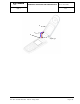
REMOVING / REPLACING THE LOUDSPEAKER
1/2
Ref. SCT U38 SSC DTS 0016 - Index A – May 6, 2004 Page 5-34
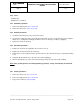
6.58 Tools :
- Tweezers
- A 0.6mm torx screwdriver
- Soldering iron
- Flat screwdriver
6.59 Preliminary operation
1. Remove the battery pack ( Proc sheet 0 01).
2. Remove the back cover ( Proc sheet 1 01).
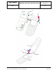
6.60 Removal procedure :
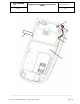
1. Unstick the ground tape (2) of the electronic board (1)
2. Unsolder the loudspeaker wires (3) and the flip ground wire (4) on the electronic board (1), by noting the
wiring sense ( loudspeaker and flip ground wires colours can change according to supplying)
3. Remove the electronic board (1)
4. Press the hinge (6) inside the front cover by means of (curved) tweezers to release the equipped flip (5)
5. Remove the equipped flip (5)
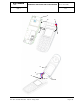
6.61 Placement procedure :
1. Position the equipped flip (5) in its housing by inserting the loudspeaker wires (3) and the flip ground wire
(4) into the front cover
2. Press firmly the hinge (6) with a flat screwdriver, to fix the equipped flip (5) on the front cover
3. Replace the electronic board in its housing (3)
4. Flux the place of the loudspeaker wires (3) and solder it on the electronic board (1), respecting the wiring
sense
5. Solder the flip ground wire (4) on the side of the radio shielding (8)
6. Stick the ground tape (2) on the electronic board (1) by fixing correctly on the radio shielding
Nota: If the ground tape have been damaged during operations, change automatically the LCD foam
for ESD.
6.62 Further operations :
1. Remove the back cover ( Proc sheet 1 01).
2. Remove the battery pack ( Proc sheet 0 01).