SITE TECHNICAL DOCUMENTATION myC-1 Doc. No.
Technical Site Documentation myC-1 NO DISCLOSURE AGREEMENT This document is SAGEM SA property. It can not be copied or communicated in all or part without written authorisation. Ref.
Technical Site Documentation myC-1 CONTENTS CHAPTER 1 - FOREWORD 1.1 HOW TO USE THE SITE TECHNICAL DOCUMENTATION.............................................................1-1 1.2 ABREVIATIONS .................................................................................................................................1-2 1.3 COMMENTS SHEET..........................................................................................................................1-3 CHAPTER 2 - DESCRIPTION - OPERATION 2.
Technical Site Documentation myC-1 SYMPTOM SHEET 05 : KEYPAD….. ......................................................................................................3-12 SYMPTOM SHEET 06 : RING TONES....................................................................................................3-13 SYMPTOM SHEET 07 : VIBRATE .............................................….………………………………………..3-14 SYMPTOM SHEET 08 : LOUDSPEAKER………………………………………………..............................
Technical Site Documentation myC-1 LEVEL 2 MAINTENANCE ............................................................................................................................5-21 PROCEDURE SHEET 2 01 : REMOVING AND REPLACING THE MICROPHONE..............................5-22 PROCEDURE SHEET 2 02 : REMOVING AND REPLACING THE CHARGER CONNECTOR ............5-24 PROCEDURE SHEET 2 03 : REMOVING AND REPLACING THE EQUIPPED FLIP ...........................
Technical Site Documentation myC-1 CHAPTER 1 - FOREWORD This document is common to all phones in the SAGEM. It is composed of independent sheets: − Symptom sheets = Symp Sheet XX − Test and check sheet = Test Sheet XX − Maintenance procedure sheet = Proc Sheet X XX The applicability of a procedure is indicated in the independent sheets title block: − All types = GSM 850/900, GSM 1800/1900 and dual band. These sheets are updated from time to time in Technical Information Bulletins (TIB).
Technical Site Documentation myC-1 All sheets include illustrations to make it easier to read the procedure. Chapter 1 : Foreword, describes general data about this document. Chapter 2 : Description - Operation, describes general data and options available in the myC-1. Chapter 3 : Symptoms, contains troubleshooting procedures to be carried out on equipment. Chapter 4 : Tests and checks, contains tests and check procedures to be performed on the equipment.
Technical Site Documentation myC-1 1.3 SIM Subscriber Identify Module SMS Short Message Service SMS CB Short Service Message Cell Broadcast SMT Sagem Mobiles Tools TFT Thin Film Transistors USSD Unstructured Supplementary Service Data VGA Video Graphics Array WiFi Wireless Fidelity WAP Wireless Application Protocol WSP Wireless Session Protocol COMMENTS SHEET Broad experience is very beneficial in several respects.
Technical Site Documentation - myC-1 Document title: Site Technical Document for myC-1 Reference : SCT U38 SSC DTS 0016 Date : Please fill in the following table : Excellent Good Fairly good Passable Easy to find the required information Clarity of information provided Quality and accuracy of information given Document outline Document presentation and appearance Quality of illustrations General satisfaction Do you think this document could be improved ? if so, how ? : Improve the overall view Improve
Technical Site Documentation - myC-1 CHAPTER 2 - DESCRIPTION - OPERATION 2.
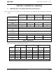
Technical Site Documentation - myC-1 Table 3 shows power classes : Class 1 Class 2 Class 3 Class 4 Class 5 SM 850 / 900 43 dBm 39 dBm 37 dBm 33 dBm 29 dBm GSM 1800 30 dBm 24 dBm 36 dBm - - GSM 1900 30 dBm 24 dBm 33 dBm - - Table 3: RF power classes Ref.
Technical Site Documentation - myC-1 2.2 REMINDERS ABOUT THE CHARACTERISTICS AND OPTIONS OF myC-1 Remark: This information is given for guidance, and is in no way contractual characteristics vary according to customers and countries. Size Dimension (LxWxH, mm) Weight (g) Volume (cm3) Power Management Battery type Charging time Talk time (TW.09) Standby time (TW.
Technical Site Documentation - myC-1 Instant messaging (IMPS) - Chat Notification Predictive text input Video & Images Camera Image features Video Player Image Format Audio Audio Recorder Audio player Polyphonic ringtones Audio formats Entertainment Wallpaper Screensaver Clock display Icons Embedded Games Java OTA Downloads Protocol supported Wallpaper / screensaver Animation Menu icon Games Ringtone Music Java application Voice features Mute mode Integrated handsfree mode Address book features Call group
Technical Site Documentation - myC-1 International access key Personal Management Features Calculator Alarm Clock Stop watch Organizer To Do Voice recorder Currency converter Languages Compatible Accessories Data cord Universal charger Hands free kit Yes, by long press on 0 SPECIAL FEATURES (cont’d) MEMORY Internal phone book (positions) Messaging memory SMS/EMS/MMS/Email (positions) Redial list (positions) Additional multimedia memory Embedded memory (Max size for total user objects) Ref.
Technical Site Documentation - myC-1 2.3 IDENTIFICATION All phones are identified with an identification label sticked on the antenna. 2.3.1 Illustration 2.3.2 Description a : IMEI (bar code), b : IMEI (15 characters) c : Reference of product / aesthetic used (bar code) d: Reference of product / aesthetic used ( 9 characters) e :Module serial number (bar code) f: Module serial number (10 characters), g : Date code + Manufacturing level + Production area Indication, Ex.
Technical Site Documentation - myC-1 2.3.3 Description after repair A new sticker is positioning by Repairing Centre near the sim card connector: This extra line will appear if the mobile has already been repaired. - CRA XXX N° of CRA, - 203/N03 Date of repair: (203) repairing day, (03) last digit of year (03→2003). Ref.
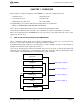
Technical Site Documentation - myC-1 2.4 PHONE BLOCK DIAGRAM 2.4.1 myC-1 block diagram BASEBAND RADIO LCD / KEYPAD 2.4.2 Standards and environment Conformance Document SAGEM SA declare under its sole responsibility that the product Dual Band GSM/DCS Type B2003 conforms to the requirements of the following EEC directives: EEC Directive 1999/5/CE Safety EN 60950 EMC EN 301 489-1 / EN 301 489-7 Low voltage directive 73/23/CEE Network 3GPP TS 51.010-1 v 5.2.0 selected with GCF-CC v 3.10.
Technical Site Documentation - myC-1 2.5 EQUIPEMENTS The description and operation of SAGEM myC-1 are given in the "User’s handbook" supplied with the phone. This chapter only describes equipment that operates with the myC-1 phones . 2.5.1 Battery packs Over view 2.5.1.1 2.5.1.2 Characteristics Technology Weight Voltage capacity Li-ion 22g 3,6 V / 550 mA/H Description Li-ion type batteries are used.
Site Technical Documentation - GSM 900/1800 - Serie 3000 2.5.1.3 Charging time The following table shows typical charging times for different batteries. 2.5.2 2.5.2.1 Battery 500 mA regulated chargers "Simple" unregulated chargers 230 V Nom. (110 V Nom.) Li-ion 2h 2h50 Mains modules Description These mains power supply modules accept large dynamic variations in the power supply network. They are available for a number of connector types: 2.5.2.2 − E.
Site Technical Documentation - GSM 900/1800 - Serie 3000 CHAPTER 3 - SYMPTOMS 3.1 GENERAL After you have received the customer return sheet (Proc Sheet 3 02), carry out the troubleshooting procedure. This chapter will help you to identify the defective element(s), using the troubleshooting table. It contains flow charts broken down by fault type. Each flow chart describes the procedure to be followed and contains cross references to tests or maintenance.
Site Technical Documentation - GSM 900/1800 - Serie 3000 Ref.
Site Technical Documentation - GSM 900/1800 - Serie 3000 3.
Site Technical Documentation - GSM 900/1800 - Serie 3000 Code Indicated fault Procedure E1 Defective loudspeaker (hails) Symp Sheet 08 E2 Loudspeaker voice distortion Symp Sheet 08 E3 Defective microphone Symp Sheet 08 E4 Microphone voice distortion Symp Sheet 08 E5 Vibrating device malfunction (depending on models) Symp Sheet 07 E6 Defective audio connector Symp Sheet 08 F1 No network localisation Symp Sheet 02 F2 Intermittent calls drop Symp Sheet 02 F3 Network temporary drop
Site Technical Documentation - GSM 900/1800 - Serie 3000 3.
Site Technical Documentation - GSM 900/1800 - Serie 3000 Message Meaning "PUK2 BLOCKED" Following input errors "CODE ERROR" The phone code input for locking the mobile is incorrect "NOT AVAIL." Service not implemented in the network "TRY AGAIN" Following a network problem "NETWORK BUSY" "Problems" related to the network and Communications "WAIT" "Problems" related to the network and Communications "UNBLOCK?" "Problems" related to the SIM card "MEMO REC.
Site Technical Documentation - GSM 900/1800 - Serie 3000 3.5 LIST OF OBSERVED DEFECTS A SAGEM code is assigned to each confirmed defect. This code should be entered on Proc Sheet 3 01, SAGEM Factory Return, if the phone to be repaired is returned to SAGEM (see chapter 5). 3.6 NEW PROBLEM DETECTED PROCEDURE When a new problem is detected: 1- The concerned technician fills a precise report using the document located in the ARC Kit : NPD report SAV GSM 277 V1.doc (see ANNEX A2.
Site Technical Documentation - GSM 900/1800 - Serie 3000 SYMPTOM SHEETS Ref.
ENDURANCE, BATTERY, CHARGER PROBLEM myC-1 Symp Sheet 01 1/1 Test the charger Test Sheet 01 No Ok? Replace the Standard charger Yes Test the battery Test Sheet 02 No Ok? Replace the battery Proc Sheet 0 01 Yes End ________________________________________________________________________________________________ Ref.
COMMUNICATION PROBLEM Symp Sheet 02 myC-1 1/1 Do the Wavetek test Test sheet 04 No Radio problem ? Non yes End Return to SAGEM Proc sheet 2 08 or Proc 3 01 ________________________________________________________________________________________________ Ref.
NO FAULT GIVEN myC-1 Symp Sheet 03 (Mobile expertise) 1/1 Charger Test Test Sheet 02 Fault found ? yes No End Battery test Test sheet 02 Fault found ? Yes No display test ( HOTLINE menu) Test Sheet 03 Fault found ? End Yes No Radio Test (wavetek) Test Sheet 04 Fault found ? End Yes End No Return to SAGEM Fiche Proc 2 08 ou Proc 3 01 ________________________________________________________________________________________________ Ref.
DISPLAY PROBLEM Symp Sheet 04 myC-1 1/1 Test the display with the "Hotline" menu Black screen Test Sheet 03 Yes Ok ? No End Replace the display Proc Sheet 2 06 Test the display with the "Hotline" menu Test Sheet 03 Ok ? Yes No Return to SAGEM Proc Sheet 2 08 or Proc 3 01 Ref.
KEYPAD PROBLEM Symp Sheet 05 myC-1 1/1 Set the “Keypad beep” function Test the keypad by listening to the key beep Yes Ok? No End Replace a new metal dome Proc Sheet 1 03 Repeat the keypad test Yes Ok? No End Return to SAGEM Proc Sheet 2 08 or Proc 3 01 Ref.
RING TONES PROBLEM Symp Sheet 06 myC-1 1/1 Unselect “Vibrate only” function "SOUNDS/VIBRATE" menu Check ring tones with incoming call Yes Ok ? No End Replace the loudspeaker Proc Sheet 2 05 yes Ok ? No End Return to SAGEM Proc Sheet Proc 3 01 Ref.
VIBRATING DEVICE Symp Sheet 07 myC-1 1/1 Test the vibrating device with the hotline menu Test Sheet 03 Ok ? Yes No End Replace the vibrating device Proc Sheet 1 05 Test the vibrating device with hotline menu Test Sheet 03 Ok ? Yes No Return to SAGEM Proc Sheet 2 08 or Proc 3 01 End ________________________________________________________________________________________________ 29/03/01Ref.
Technical Site Documentation myC-1 Do the Wavetek test Test Sheet 04 No Audio problem ? Yes Replace the microphone and/ or the loudspeaker if necessary Proc Sheet 2 01 Proc Sheet 2 05 Fin Perform radio test Test Sheet 04 Yes Ok ? No Return to SAGEM Proc sheet 2 08 Or Proc 3 01 End
Technical Site Documentation myC-1 CHAPTER 4 - TESTS AND CHECKS 4.1 ABOUT TESTS Tests and checks are made after the troubleshooting procedures (chapter 3) and before the maintenance procedures (chapter 5). They are broken down into modules and are sorted by types of confirmed faults. The user must be equipped with special test tools in order to carry out the tests. 4.2 TEST TOOLS The references of SAGEM tools, listed hereafter, are given in Appendix 1 : Composition table.
Technical Site Documentation myC-1 TEST SHEET
CHARGER TEST myC-1 Test Sheet 01 1/1 Test description This test checks the various battery chargers. Test procedure 1. 2. 3. 4. Check visually the charger connector. Connect the charger to be tested to the mobile . Access to the "HOTLINE" menu by pressing on the ∇ key and then the * key. Select the APPLICATION menu and the BATTERY STATUS to check that the battery voltage is increasing Ref.
BATTERY TEST myC-1 Test Sheet 02 1/1 Test description This test allows to test the various batteries. Required tools − CADEX C7000 / C7200 / ASTRATEK − myC-1 adapters, − myC-1 Ammeter interface − a voltmeter (minimum impedance 20 kΩ per Volt in DC). Test procedure 1. Insert battery on ammeter interface 2. Measure the identification resistor between the Z poles : 3. Li-Ion batteries : 120kΩ Ω ( tolerance = 117kΩ Ω - 123kΩ Ω, according to the surrounding temperature) 4.
"HOTLINE" MENU myC-1 Test Sheet 03 1/1 Access to the "HOTLINE" menu Access to the "HOTLINE" menu is possible with a powered up mobile. The "HOTLINE" menu is accessed by pressing on the ∇ key and then the * key. Enter the corresponding code (bold) to choose the menu to be viewed. To go out the "HOTLINE" menu, press successively on the C key to return at the operational screen of the mobile. Description of the myC-1 "HOTLINE" menu 1 APPLICATION • BATTERY : gives the value of the battery voltage.
Site Technical Documentation –myC-1 Test description This test tests myC-1 phones during a call. Required tools − A Wavetek − A RF coupler or a myC-1 interface. − A myC-1 calibration tool − Test procedure 1. Position the calibration tool first on the RF coupler to calibrate it 2. 3. 4. 5. 6. Position the myC-1 module on the RF coupler Switch the Wavetek on and press on "AUTOTEST". Choose the corresponding program using the "UP" and "DOWN" arrows.
Site Technical Documentation –myC-1 CHAPTER 5 - MAINTENANCE PROCEDURES TECHNICAL WORK LEVELS There are four technical work levels: Level 0, Level 1, Level 2, Level 3. Each level represents a maintenance degree that depends on which elements are to be removed.
Site Technical Documentation –myC-1 5.2 SHORT LOOP PROCESS 1. Initialisation From the communication by Sagem and the reception of the concerned products by the short loop process, the Repair Centre shall comply with the above procedure. The application of the Short loop process will end when received the authorisation of repairing given by Sagem. 2.
Site Technical Documentation –myC-1 - The under- warranty handsets and accessories declared No Fault Found (NFF) shall be exchanged to the end-users except previous communication of Sagem. - The Out of warranty handsets and accessories (oxidation, shocks, …) will be repaired by the Repair Centre after acceptation by the customer of an estimate according to the Sagem out of warranty repair prices communicated. - The under- warranty and out of warranty handsets shall be sent to Sagem Montauban.
Site Technical Documentation –myC-1 6. Procedure From the beginning date of the Short loop process application and minimum each week, the Repair Centre shall ship the products (handsets and accessories) to Sagem Montauban. 61. Handsets : - MRA Procedure for the after-Sales products ( one MRA number for the products concerned by the short loop). - MRA Procedure for DOA products ( one MRA DOA number for the products concerned by the short loop) if the Repair Centre is authorised to treat the DOA products.
Site Technical Documentation –myC-1 8 Additional information about the no fault found In any case: Ask to the end-user the frequency of the defect and the circumstances of its apparition (during an incoming or out-going call, while playing, while downloading, etc.). Try to answer the questions: Where? When? How? • • If the customer complains about a “Power supply / charging” failure : (shutting down of the mobile, problem of booting, etc.
Site Technical Documentation –myC-1 LEVEL 0 MAINTENANCE Ref.
REMOVING / REPLACING THE BATTERY Proc Sheet 0 01 myC-1 6.1 Tools : 6.2 - Not applicable 6.3 Preliminary operation : 6.4 - Switch off the mobile phone 6.5 Removal procedure : 1/2 1. Unlock the battery pack (1) , by pushing the lock button (2) upwards and extract it by mean of two nicks (3). 2. Take out the battery (1) by first extracting the lower section. 6.6 Placement procedure : 1. Replace the battery pack (1) by engaging top hooks first . 2.
REMOVING / REPLACING THE BATTERY myC-1 Proc Sheet 0 01 2/2 1 2 3 Ref.
REMOVING / REPLACING THE BATTERY myC-1 Ref.
REMOVING / REPLACING THE ANTENNA myC-1 6.7 Proc Sheet 0 02 1/2 Tools : - Not applicable 6.8 Preliminary operation : 1. Switch off the mobile phone 6.9 Removal procedure : 1. Unscrew the antenna (1) of the back cover (2) 6.10 Placement procedure : 2. Screw the new antenna (1) into the back cover (2) 6.11 Further operations 1. Carry out radio test (Test Sheet 04). 6.12 Ref.
REMOVING / REPLACING THE ANTENNA Proc Sheet 0 02 myC-1 2/2 1 2 Ref.
Site Technical Documentation –myC-1 LEVEL 1 MAINTENANCE ________________________________________________________________________________________________ Ref.
REMOVING / REPLACING BACK COVER myC-1 Proc Sheet 1 01 1/2 6.13 Tools : - A 0.6mm torx screwdriver 6.14 Preliminary operation 1. Remove the battery pack ( Proc sheet 0 01). 6.15 Removal procedure : 1. On the back cover, unscrew the four attachment screws (4) . 2. Lift delicately the back cover (1) up beginning by the lower side 3. Remove rear cover (1) 6.16 Placement procedure : 1. Replace the cover by engaging top hooks first . 2.
REMOVING / REPLACING THE BACK COVER myC-1 Proc sheet 1 01 2/2 1 2 Ref.
REMOVING / REPLACING THE ELASTOMER KEYPAD Proc Sheet 1 02 myC-1 1/2 6.18 Tools : - A 0.6mm torx screwdriver 6.19 Preliminary operation 2. Remove the battery pack ( Proc sheet 0 01). 3. Remove the back cover ( Proc sheet 1 01). 6.20 Removal procedure : 1. Unstick the ground tape (2) of the radio shielding on the electronic board. 2. Turn the electronic board round to liberate it from the front cover (1) 3. Remove the elastomer keypad (2) from the front cover (1). 6.21 Placement procedure : 1.
REMOVING / REPLACING THE ELASTOMER KEYPAD myC-1 Proc Sheet 1 02 2/2 2 1 3 Ref.
REMOVING / REPLACING THE METAL DOME myC-1 Proc Sheet 1 03 1/2 6.23 Tools : - A 0.6mm torx screwdriver - Gloves - Metal dome Jig Tweezers 6.24 Preliminary operation This procedure must be performed by a technician with gloves. 1. Remove the battery pack ( Proc sheet 0 01). 2. Remove the back cover ( Proc sheet 1 01). 6.25 Removal procedure : 1. Turn the electronic board round to liberate it of the front cover 2. Remove the metal dome of the electronic board 6.
REMOVING / REPLACING THE METAL DOME Proc Sheet 1 03 myC-1 2/2 1 2 Ref.
REMOVING / REPLACING THE SIM LOCKER myC-1 Proc Sheet 1 04 1/2 6.28 Tools : - A 0.6mm torx screwdriver 6.29 Preliminary operation : 1. Remove the battery ( Proc sheet 0 01). 2. Remove the SIM card . 3. Remove the back cover ( Proc sheet 1 01). 6.30 Removal procedure : 1. On the back cover (2), looked at from the battery side ,press firmly the SIM locker (1) until its extraction . 2. Remove the SIM cover (1). 6.31 Placement procedure : 1.
REMOVING / REPLACING THE SIM LOCKER myC-1 Proc Sheet 1 04 2/2 1 2 ________________________________________________________________________________________________ Ref.
REMOVING / REPLACING THE VIBRATING DEVICE myC-1 Proc Sheet 1 05 1/2 6.33 Tools : - A 0.6mm torx screwdriver - Tweezers 6.34 Preliminary operation 1. Remove the battery ( Proc sheet 0 01). 2. Remove the back cover ( Proc sheet 1 01). 6.35 Removal procedure : 1. Remove, with the tweezers, the vibrating device (1) in its housing . 6.36 Placement procedure : 1. Put the vibrating device in its housing, respecting the foolproof device 6.37 Further operations : 1. Replace the back cover ( Proc sheet 1 01). 2.
REMOVING / REPLACING THE VIBRATING DEVICE myC-1 Proc Sheet 1 05 1/2 1 ________________________________________________________________________________________________ Ref.
Site Technical Documentation –myC-1 LEVEL 2 MAINTENANCE ________________________________________________________________________________________________ Ref.
REMOVING / REPLACING THE MICROPHONE Proc Sheet 2 01 myC-1 1/2 6.38 Tools : - A 0.6mm torx screwdriver - Soldering iron 6.39 Preliminary operation 1. Remove the battery pack ( Proc sheet 0 01). 2. Remove the back cover ( Proc sheet 1 01). 6.40 Removal procedure : 1. Unstick the ground tape (2) of the electronic board (1) 2. Turn the electronic board (1) round to liberate it from the front cover 3. Unsolder the microphone (2) on the electronic board (1) 4. Remove the microphone (1) 6.
REMOVING / REPLACING THE MICROPHONE Proc sheet 2 01 myC-1 2/2 1 2 3 Ref.
REMOVING / REPLACING THE CHARGER CONNECTOR Proc Sheet 2 02 myC-1 1/2 6.43 Tools : - A 0.6mm torx screwdriver - Soldering iron 6.44 Preliminary operation 1. Remove the battery pack ( Proc sheet 0 01). 2. Remove the back cover ( Proc sheet 1 01). 6.45 Removal procedure : 1. Unstick the ground tape (2) of the electronic board (1) 2. Turn the electronic board (1) round to liberate it from the front cover 3. Unsolder the charger connector (2) on the electronic board (1) 4. Remove the charger connector (1) 6.
REMOVING / REPLACING THE CHARGER CONNECTOR myC-1 Proc sheet 2 02 2/2 1 2 Ref.
REMOVING / REPLACING EQUIPPED FLIP myC-1 Proc Sheet 2 03 1/2 6.48 Tools : - Tweezers - A 0.6mm torx screwdriver - Soldering iron - Flat screwdriver 6.49 Preliminary operation 1. Remove the battery pack ( Proc sheet 0 01). 2. Remove the back cover ( Proc sheet 1 01). 6.50 Removal procedure : 1. Unstick the ground tape (2) of the electronic board (1) 2.
REMOVING / REPLACING THE EQUIPPED FLIP Proc sheet 2 03 myC-1 2/2 1 8 2 Ref.
REMOVING / REPLACING THE EQUIPPED FLIP myC-1 Proc sheet 2 03 2/2 5 3 7 4 Ref.
REMOVING / REPLACING THE FRONT COVER myC-1 Proc Sheet 2 04 1/2 6.53 Tools : - Tweezers - A 0.6mm torx screwdriver - Soldering iron 6.54 Preliminary operation 1. Remove the battery pack ( Proc sheet 0 01). 2. Remove the back cover ( Proc sheet 1 01). 6.55 Removal procedure : 1. Unstick the ground tape (2) of the electronic board (1) 2.
REMOVING / REPLACING THE FRONT COVER Proc Sheet 2 04 myC-1 2/2 1 8 3 2 4 5 3 7 4 6 9 Ref.
REMOVING / REPLACING THE FRONT COVER myC-1 Ref.
REMOVING / REPLACING THE LOUDSPEAKER myC-1 Proc Sheet 2 05 1/2 6.58 Tools : - Tweezers - A 0.6mm torx screwdriver - Soldering iron - Flat screwdriver 6.59 Preliminary operation 1. Remove the battery pack ( Proc sheet 0 01). 2. Remove the back cover ( Proc sheet 1 01). 6.60 Removal procedure : 1. Unstick the ground tape (2) of the electronic board (1) 2.
REMOVING / REPLACING THE LOUDSPEAKER Proc sheet 2 05 myC-1 2/2 1 8 3 2 4 5 3 7 4 Ref.
REMOVING / REPLACING THE LOUDSPEAKER myC-1 Ref.
REMOVING / REPLACING THE DISPLAY myC-1 Proc Sheet 2 06 1/1 Nota: This operation needs particulars tools. The electronic board shall return to SAGEM centre. ________________________________________________________________________________________________ Ref.
REMOVING / REPLACING THE ELECTRONIC BOARD myC-1 Proc Sheet 2 07 1/2 6.63 Tools : - Soldering iron - A 0.6mm torx screwdriver 6.64 Preliminary operation 1. Remove the battery pack ( Proc sheet 0 01). 2. Remove the back cover ( Proc sheet 1 01). 6.65 Removal procedure : 1. Unstick the ground tape (2) of the electronic board (1) 2.
REMOVING / REPLACING THE ELECTRONIC BOARD Proc Sheet 2 07 myC-1 2/2 3 4 2 5 6 1 ________________________________________________________________________________________________ Ref.
ELECTRONIC BOARD EXCHANGE Proc Sheet 2 08 myC-1 1/3 6.68 Preliminary operation 1. Control of the IMEI label integrity 2. Remove the electronic board (Proc sheet 2 06) 3. Control of any oxidation marks (on the electronic board and under the metal dome) 6.69 Return procedure : (a) The electronic boards are packaged in individual electrostatic envelopes.
ELECTRONIC BOARD EXCHANGE Proc sheet 2 08 myC-1 2/3 Example of electronic boards packaging : Electronic board metal dome with ESD shielding bag Humidity absorber Boards packaging SAGEM -> ARC Boards packaging ARC -> SAGEM B 3 Write the defect code on the label ESD shielding bag closed by the product label ESD shielding bag closed by the IMEI label ________________________________________________________________________________________________ Ref.
ELECTRONIC BOARD EXCHANGE myC-1 Proc sheet 2 08 2/3 SAGEM electrostatic shielding box Reference 20 boards: 27441180-4 Reference 100 boards: 27 511110-6 ________________________________________________________________________________________________ Ref.
ELECTRONIC BOARD EXCHANGE myC-1 Proc sheet 2 08 3/3 Electronic board exchange process Detection of N3 defect : See the Technical documentation Mobile phone with N3 deffect -Check oxidation under the metal dome . Remove the defect electronic board Proc 2.
Site Technical Documentation –myC-1 IMPORTANT Mobile packaging sent to SAGEM S.A. : Follow the Proc sheet 2 07 Packaging for swap or mobile components storage : The swap and the mobile components must be stored with a particular care especially for the most sensible component (Display , loudspeaker etc…). ________________________________________________________________________________________________ Ref.
Site Technical Documentation –myC-1 LEVEL 3 MAINTENANCE ________________________________________________________________________________________________ Ref.
RETURN TO SAGEM FACTORY Informations CRA/CRA information : Nom/Name : Rue /Street : Ville / City : Code postal /Poscode : Pays/Country Telephone /Phone : Nom du produit/product : Date d' achat/Date of purchase Code SAGEM A1 A2 A3 A5 A6 A7 A10 Proc Sheet 3 01 Garantie/Warranty : Garantie standard/Standard warranty : Déjà réparé/préviously repaired : Hors garantie/Out of warranty : Garantie expirée /Expired warranty : Mauvaise utilisation / Misuse : N°Série/Sérial n° : N°IMEI : Type de défauts Type of fau
Site Technical Documentation –myC-1 C ach et du V end eur/D ealer's S tam p : N om du produit/product : D ate d' achat/D ate of purchase G arantie/W arran ty : G arantie standard/Standard w arranty : D éjà réparé/préviously repaired : C ode S AG E M T ype de défaut In fo rm ation s C lien t /Info rm ation : N om /N am e : R ue /Street : Ville / C ity : C ode postal /Postcode : Pays/C ountry T elephone /Phone : N ° S érie/Sérial n° : N ° IM E I : H ors garan tie/O ut o f w arranty : G arantie expirée /E x
Site Technical Documentation –myC-1 CHAPTER 7 - TECHNICAL INFORMATION BULLETIN 7.1 PURPOSE The purpose of the Technical Information Bulletin (TIB) is to complete the maintenance operations described in this document. They give to the repair centers the complementary technical informations and the corrective procedures to be applied to maintain the product following it' s evolution. 7.2 APPLICATION The Technical Information Bulletin (TIB) are reference and must be applied by the repair centers.
Site Technical Documentation –myC-1 CHAPTER 8 - ILLUSTRATED PART CATALOG 7.1 myC-1 spare parts ASSEMBLY 10 QTY 1 DESIGNATION PHOTOS Pack battery 15 4 RLX 1,8-6 screw 20 1 Back cover 25 1 Vibrating device 30 1 SIM locker 35 1 Antenna 40 6 Electronic board 45 1 Microphone 50 1 Charger connector 55 1 LCD foam for ESD Ref.
Site Technical Documentation –myC-1 60 1 Front cover 65 1 Equipped flip Ref.
Site Technical Documentation –myC-1 10 20 15 25 35 40 55 30 45 Ref: SCT U38 SSC DTS 0016 – Index A – May 6, 2004 50 Page 1-5
Site Technical Documentation –myC-1 65 60 Ref: SCT U38 SSC DTS 0016 – Index A – May 6, 2004 Page 1-6
Site Technical Documentation –myC-1 CHAPTER 9 - COMPOSITION TABLE 9.1 PURPOSE This chapter contains the SAGEM codes of articles mentioned throughout the Site Technical Documentation. 9.