
Installation guide


Diagnostic LEDs
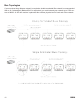
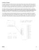
The MAC-4R panel has 23 diagnostic LED’s which tell the Technician at a glance real time Point
Status as well as Main Power Status, Back-Up Battery in Use, Panel Transmit Status, and various
processors health.
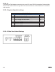
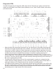
• When the MAC-4R control panel frst powers up, you should have 2 Red LEDs ON (Power and
Transmit) in the upper left hand side of the controller. You’ll notice that the Transit LED will fash
every once in a while. It fashes off when ittransmits to the Host computer. Upon boot, if no prior
confguration has been detected, the controller will run through a Power ON Ram Test. The Host
computer should receive two RAM Pass messages: one from P1 and the other from P2.
• If any of the Green Service LEDs are ON for processors P1 (D38), P2 (D37), P3 (D14), or P4
(D15) it’s bad news. There are three check sums that have to match for the processor to boot and
go on-line. The most common problem is static electricity discharge knocking out a ROM chip. If
this occurs, call the factory for help.
• The Yellow LED (D50) will only come on if the control panel is running at a voltage less than
14VDC. Minimum voltage specifed is 18 volts. When the controller gets down to fewer than 11
volts the low battery cut of relay disconnects the controller from battery power.
• The LEDs across the bottom of the control panel provide real-time point status. If the LED is ON,
the point is closed. When a new controller is powered up, the address of the control needs to be
set and an initial download of Settings must be transferred into the controller before it will start
transmitting input or output status to the Host computer.
20
REV 2.0