MorphoAccess TM Installation Guide MA500 Series Produced by Sagem Sécurité Copyright ©2007 Sagem Sécurité www.sagem-securite.
2 SAGEM Sécurité document. Reproduction and disclosure forbidden.
CONTENTS INTRODUCTION 5 SAFETY INSTRUCTIONS 6 EUROPE INFORMATION : USA INFORMATION CANADIAN INFORMATION 6 7 7 GENERAL DESCRIPTION 8 MA5XX VERSIONS INSTALLATION PROCEDURE 10 STAGE 1: DRILLING THE MOUNTING HOLES STAGE 2: MOUNTING THE METAL CHASSIS ASSEMBLY STAGE 3: CONNECTING THE CHASSIS ASSEMBLY TO THE COVER ASSEMBLY STAGE 4: CLOSING MORPHOACCESS™ 10 11 12 13 OMA5XX VERSIONS INSTALLATION PROCEDURE 14 STAGE 1: DRILLING THE MOUNTING HOLES STAGE 2 : OMA5XX FIXING STAGE 3 : OMA5XX CABLING STAGE 4
MORPHOACCESSTM MA5XX SERIES TECHNICAL CHARACTERISTICS 26 MAN MACHINE INTERFACE BIOMETRY PERIPHERALS INTERFACES POWER SUPPLY SIZE AND WEIGHT ENVIRONNEMENTAL CONDITIONS 26 26 26 27 27 28 RECOMMENDATIONS 29 AREAS CONTAINING COMBUSTIBLES GENERAL PRECAUTIONS SPECIFIC PRECAUTIONS FOR RADIO TERMINALS ETHERNET CONNECTION DATE / TIME SYNCHRONIZATION CLEANING PRECAUTIONS WARNING BIOMETRICS TERMINALS HOT LINE 29 29 29 30 30 30 30 30 APPENDIX 1 - FINGERPRINT PLACEMENT RULES 31 APPENDIX 2 – RELATED DOCUMENTS
INTRODUCTION Congratulations for choosing the SAGEM MorphoAccess™1 Automatic Fingerprint Recognition Terminal. MorphoAccess™ provides an innovative and effective solution for access control applications using Fingerprint Verification or/ and Identification. Among a range of alternative biometric techniques, the use of finger imaging has significant advantages: each finger constitutes an unalterable physical signature which develops before birth and is preserved until death.
SAFETY INSTRUCTIONS The installation of this product should be made by a qualified service technician and should conform to all local codes. It is strongly recommended that a class II power supply at 12 V ±5% and 0.75 A. min be used in accordance with Safety Electrical Low Voltage (SELV) parameters. The 12 V power supply cable length should not exceed 5 meters.
USA information Caution: FCC part 15 certificates are pending. This device complies with part 15 of the FCC Rules. Operation is subject to the following two conditions: (1) This device may not cause harmful interference, and (2) this device must accept any interference received, including interference that may cause undesired operation. Changes or modifications not expressly approved by the party responsible for compliance could void the user’s authority to operate the equipment.
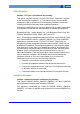
GENERAL DESCRIPTION MA5xx versions Display 128 x 64 dots Sensor Function keys MIFARE Keyboard Card reader ( MA520 / 521 only ) Mounting keyholes Anti-theft entry Cable entry Metal chassis MorphoAccess™ supplies: 1 Cover assembly with Chassis and 2 Secured screws for fixation 1 Secured screwdriver Torx 20 1 Chassis fixation kit ( 4 fixations and screws , 1 anti theft block ) 8 SAGEM Sécurité document. Reproduction and disclosure forbidden.
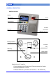
OMA5xx versions Protective visor Display Sensor 128 x 64 dots Function keys MIFARE Card reader ( MA520 / 521 only ) Keyboard 4 Mounting slots Outdoor MorphoAccess™ supplies: 1 Cover assembly with chassis and protective visor 1 Secured screwdriver Torx 10 1 Chassis fixation kit ( 4 fixations and screws ) SK-53018-03 SAGEM Sécurité document. Reproduction and disclosure forbidden.
MA5XX VERSIONS INSTALLATION PROCEDURE Stage 1: Drilling the mounting holes Mounting and cable entry hole location (rear view) a) Using the dimensional drawing in Appendix 3, drill 2 holes for the mounting keyholes screws so that the cable entry is in a suitable position for cabling. b) Drill the hole for the third screw in the center of the slot so that it is possible to correct the position later, if necessary. c) The mounting screws must be 5 mm diameter maximum. 10 SAGEM Sécurité document.
Stage 2: Mounting the metal chassis assembly Anti theft switch Cable entry Terminal block board Chassis bold receivers a) Disconnect the ribbon cable between the motherboard and the terminal block board so that the assembly shown above can be detached from the rest of MorphoAccess™. b) Pass the connecting cables through the cable entry. c) Position the chassis assembly against the wall using the two screws in the mounting keyholes. d) Hold the chassis in place with a screw through the mounting slot.
Stage 3: Connecting the chassis assembly to the cover assembly Ribbon cable connector location Tamper switch Cover assembly Motherboard/terminal block board ribbon cable connector Chassis assembly Position of the ribbon cable as the case is closed Cover assembly The ribbon cable must be folded as shown so that the case closes easily without damaging the cable Chassis assembly 12 SAGEM Sécurité document. Reproduction and disclosure forbidden.
Stage 4: Closing MorphoAccess™ Catch for the cover assembly lip Lip When the ribbon cable has been connected between the two assemblies (see stage 3), the cover assembly is fitted to the chassis assembly. 1 The lip on the cover slides behind the chassis, to fit over the catch shown on the diagram above. 2 The cover is fitted onto the chassis by rotating it. Fit the two M4x16 assembly screws. Use screwdriver TORX 20 SK-53018-03 Assembled MorphoAccessTM SAGEM Sécurité document.
OMA5XX VERSIONS INSTALLATION PROCEDURE Stage 1: Drilling the mounting holes Mounting hole location (rear view) a) Using the dimensional drawing for OMA5xx in Appendix 3, drill holes for the four mounting bolts, vertically centered within the four slots. b) The mounting bolts must be 5 mm diameter maximum. 14 SAGEM Sécurité document. Reproduction and disclosure forbidden.
Stage 2 : OMA5xx fixing a) Remove protective visor ( 4 small caps at each corner ) before fixing OMA5xx assembly. Remove the 4 small caps at each corner of the protective visor , with a small screw driver Remove the 4 screws , with T10 screw driver supplied. b) Adjust the OMA5xx assembly in front of the 4 holes.
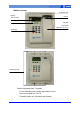
ELECTRICAL INTERFACE MA5xx Terminal block board wiring Tamper switch Relay Anti theft opto Anti theft switch Power supply source Wiegand OUT External +12V DC Dataclock OUT or Wiegand IN COM Dataclock IN RS422 / RS485 Ground security reference Power Over Ethernet 16 Ethernet Terminal block or RJ45 SAGEM Sécurité document. Reproduction and disclosure forbidden.
OMA5xx rear view and cables Power Supply source COM RS422/ 485 Tamper switch Relay Ethernet RJ45 Wiegand DataClock Wiring ( cables colors and cables positions ) is not exactly the same as previous OMA2xx/3xx family. In order to be complied with EMC directives ( See p 6 ), all cables coming from Access Control system must be shielded. Both shield wires ( OMA5xx cable , AC system cable ) must be tied together. Shield wire from OMA5xx cable is the wire without insulation.
Power Supply source MA5xx OMA5xx Power cable 1 Block 1 +12V 2 Block 2 GND/ALIM Ground In Positive 12 Volts, power supply. In Ground power supply. In Ground security reference Red Black yellow/green Power supply: Must conform to CEE/EEC EN60950 standard 9V to 16 Volts ± 5% (regulated) 1,5 Amp max ( peak ) Power may come from a 12 Volts Wiegand power supply, conforming to the Security Industry Association's Wiegand standard March 1995 , able to deliver 9 Watts.
Wiegand output wiring MA5xx OMA5xx Wiegand Dataclock cable 1 Block 1 D0 Out Wiegand D0 Green 2 Block 2 D1 Out Wiegand D1 White 3 Block 3 LED1 In Wiegand LED IN 1 (option) Brown 4 Block 4 LED2 In Wiegand LED IN 2 (option) Grey 5 Block 5 GND Ground for Wiegand Black Electrical interface conforms to the Security Industry Association's Wiegand standard March 1995, and it is 5V TTL compatible.
Wiegand input wiring MA5xx OMA5xx Wiegand Dataclock cable 1 Block 1 D0 In Wiegand D0 Blue 2 Block 2 D1 In Wiegand D1 Yellow 3 Block 3 LED Out Wiegand LED OUT 1 (option) Orange 4 Block 4 +12V Out 12 Volts Power output (150 mA max) 5 Block 5 GND Ground for Wiegand Red Black Electrical interface conforms to the Security Industry Association's Wiegand standard March 1995, and it is 5V TTL compatible.
COM RS422 serial port MA5xx OMA5xx COM RS422/RS485 cable 1 Block 1 GND Ground for RS422 Grey or White 2 Block 2 Tx- Out RS422 Negative Transmit Orange 3 Block 3 Tx+ Out RS422 Positive Transmit Orange/White 4 Block 4 Rx- In RS422 Negative Receive Green 5 Block 5 Rx+ In RS422 Positive Receive Green/White RS422 interface is a full duplex communication.
Ethernet wiring 2 ways for Ethernet wiring : - Terminal block connection ( MA5xx only ) MA5xx OMA5xx Ethernet cable 1 Block 1 RX- In Receive negative Ethernet RJ45 Pin 6 2 Block 2 RX+ In Receive positive Ethernet RJ45 Pin 3 3 Block 3 TX- Out Transmit negative Ethernet RJ45 Pin 2 4 Block 4 TX+ Out Transmit positive Ethernet RJ45 Pin 1 5 Block 5 GND Ground for shield Ethernet RJ45 Pin 7 - RJ 45 cabling connection RJ45 Pinout Signals EIA/TIA T568B color EIA/TIA T568A color C
Output relay and security switches MA5xx OMA5xx Switch/relay cable 1 Block 1 CRO Contact relay normally open 2 Block 2 CRC Contact relay normally closed Orange 3 Block 3 CR Contact relay common Yellow 4 Block 6 TSW2_1 Tamper switch Contact 1 White 5 Block 7 TSW2-0 Tamper switch Contact 0 Green 6 Block 4 ATSW1_1 Anti theft switch Contact 1 Not available 7 Block 5 ATSW1_0 Anti theft switch Contact 0 Not available Ground Not connected Red Black (*) (*) : For this interfa
“Security Loop” connection example : TSW1_0 TSW1_1 ATSW1_0 ATSW1_1 "Security Loop" Physical Access Controler Relay ratings 2 A at 30 VDC according to the safety extra low voltage requirements (62.5 VAC max, 220 VDC max and 125 VAC max) independently of the power supply. Inductive charge management require a parallel diode for a better contact lifetime.
USER INTERFACE The MorphoAccess™ terminal functions in three operational modes: access control with identification, access control with authentication or verification, and proxy mode. These various modes are detailed in the MA500 Series User Guide. Terminal configuration may be done locally ( keyboard , USB key ) or remotely (using the configuration Tool or MEMS software) , by modifying key parameter. For MA5xx terminal management , MEMS software release must be at least v6.2.
MORPHOACCESSTM MA5XX SERIES TECHNICAL CHARACTERISTICS Man Machine Interface LCD display 128 x 64 pixels Alphanumeric and function keyboard ( 12 + 4 keypad ) Color LED for information Multi tone Buzzer Clock : +/- 4sec / day ( typical conditions ) , minimum 24 hours backup Biometry Based on SAGEM MSO Biometric Module, FIPS IQS certified: 500dpi optical sensor Template Data base: 3000 persons with 2 fingers 5 x 10000 pers with 2 fingers and MA-X license option Identification: < 1,5s ( 1000 persons in datab
Power supply 9 to 16 Volts ± 5% and 1,5A peak power supply Cable cross section depends on the length 0. 75mm2 recommended. Consumption : 750mA maximum rms @12V ( < 1,5 A peak ) 350mA typical rms @12V Power Over Ethernet compatibility ( IEEE802.
Environnemental conditions Operating temperature -10 °C to + 50 °C. Operating humidity 10 % < RH < 80 %. Storage temperature -20 °C to + 70 °C. Storage humidity RH < 95 %. Hardness MA5xx : IP30 ( indoor use only ) OMA5xx : IP65 (protection against rain and dust ) Light We recommend MorphoAccess™ within controlled lighting conditions. installation Avoid direct exposure of sensor to sunlight. Avoid intensive UV lights. 28 SAGEM Sécurité document. Reproduction and disclosure forbidden.
Recommendations Areas containing combustibles It is strongly recommended that you do not install your SAGEM MorphoAccess™ in the vicinity of gas stations, petroleum processing facilities or any other facility containing flammable or combustible gasses or materials. General precautions • Do not attempt to repair your SAGEM MorphoAccess™ yourself. The manufacturer cannot be held responsible for any damage/accident that may result from attempts to repair components.
Ethernet connection It is recommended to use a category 5 shielded cable (120 OHM). It is also strongly recommended to insert a repeater unit every 90 m. Extreme care must be taken while connecting Ethernet wire to the terminal block board since a low quality connection may strongly impact the Ethernet signal sensitivity. It is recommended to connect Rx+ and Rx- with the same twisted-pair wire (and to do the same with the Tx+/Tx- using different twisted-pair wire).
APPENDIX 1 - FINGERPRINT PLACEMENT RULES To ensure a good quality contact of your finger on the terminal you must leave your finger on the sensor until the sensor light is turned off. Area containing most of the information SK-53018-03 Fingerprint Placement Fingerprint Orientation Fingerprint Inclination Fingerprint Rotation SAGEM Sécurité document. Reproduction and disclosure forbidden.
APPENDIX 2 – RELATED DOCUMENTS Administrator Information MA500 Series User Guide This document describes operating mode and terminal settings MA500 Series Configuration Application User Guide This document describes the configuration application processing MA500 Series Parameters Guide The complete description of terminal configuration files and registry keys This document gives also parameters default values.
MA500 Series Upgrade Tools User Guide Upgrade Tool user guide about firmware upgrading procedures Terminal Licence Management Download a licence in MorphoAccessTM using “Terminal Licence Manager.exe” PC application. SK-53018-03 SAGEM Sécurité document. Reproduction and disclosure forbidden.
APPENDIX 3 - DRILLING TEMPLATE MA5xx versions Anti theft block position Scale : 1 ( Real dimensions ) 34 SAGEM Sécurité document. Reproduction and disclosure forbidden.
OMA5xx versions 70 135 256 Attention : the above image dimensions do not match reality. SK-53018-03 SAGEM Sécurité document. Reproduction and disclosure forbidden.
SUPPORT Customer service SAGEM Sécurité SAV Terminaux Biométriques Boulevard Lénine - BP428 76805 Saint Etienne du Rouvray FRANCE Tel: +33 2 35 64 55 05 Hotline SAGEM Sécurité Support Terminaux Biométriques 24, Av du gros chêne 95610 Eragny – FRANCE hotline.biometrics@sagem.com Tel: + 33 1 58 11 39 19 https://www.sagem-ds.com/biometrics-customersupport/ Copyright ©2007 SAGEM Sécurité http://www.sagem-securite.com/ 36 SAGEM Sécurité document. Reproduction and disclosure forbidden.
Siège social: Le Ponant de Paris 27, rue Leblanc - 75512 PARIS CEDEX 15 - FRANCE