MorphoAccess TM 200/300 Installation Guide SAGEM MORPHO, Inc. 1145 Broadway Plaza, Suite 200 Tacoma, WA.
CONTENTS Welcome to MorphoAccess™ 1 Safety instructions 2 General description 4 Installation procedure Stage 1: Drilling the mounting holes for the metal chassis assembly Stage 2: Mounting the metal chassis assembly Stage 3: Connecting the chassis assembly to the cover assembly Stage 4: Closing MorphoAccess™ 5 5 6 7 8 How to upgrade MorphoAccess™ 200 to 300 9 Electrical interfaces Terminal block board Power supply cable COM1 RS485/422 serial port wiring COM1 Deister wiring (optional) Ethernet wiri
Power supply Size and weight Environmental conditions Storage conditions 22 22 22 22 Recommendations Areas containing combustibles General precautions 23 23 23 Appendix 1 - Ethernet color standard 24 Appendix 2 - Wiegand data format 25 Appendix 3 - ISO 7811/2-1995 - Track 2 Dataclock format 26 Appendix 4 - Reserved configuration keys 28 Appendix 5 - Morpho Product Warranty and End-User Software License 29 Drilling Template ii 32 Contents
Welcome to MorphoAccess™ Congratulations for choosing the MorphoAccess™ Automatic Fingerprint Recognition Terminal. MorphoAccess™ provides an innovative and effective solution for access control or time and attendance applications using fingerprint verification and/or identification. Among a range of alternative biometric techniques, the use of finger imaging has significant advantages: each finger constitutes an unalterable physical signature which develops before birth and is preserved until death.
Safety instructions – Please Read Before Installation WARNING: Installation must be performed by professional installers Note: These instructions for the installation of the MorphoAccess assume the installer is properly qualified as a professional, and is familiar with applicable industry standards, local building/zoning codes, and proper installation practices. Installation should not be attempted by non-professionals. You are required to use an NEC class II power supply at 12 V ± 5% and 2.5 A minimum.
CAUTION DANGER OF EXPLOSION IF BATTERY IS INCORRECTLY REPLACED. REPLACE ONLY WITH THE SAME OR EQUIVALENT TYPE RECOMMENDED BY THE MANUFACTURER. MUST BE DISPOSED OF PROPERLY. ATTENTION IL Y A DANGER D’EXPLOSION S’IL Y A REMPLACEMENT INCORRECT DE LA BATTERIE. REMPLACER UNIQUEMENT AVEC UNE BATTERIE DU MEME TYPE OU D’UN TYPE EQUIVALENT RECOMMANDE PAR LE CONSTRUCTEUR.
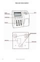
General description 4 General description
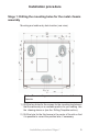
Installation procedure Stage 1: Drilling the mounting holes for the metal chassis assembly Mounting and cable entry hole location (rear view) Note: The mounting screws can not exceed 5 mm in diameter. 1) Drill the two holes for the screws for the mounting keyholes so that the cable entry is in a suitable position for your cabling. Use the drawing above or (see the Drilling Template section).
Stage 2: Mounting the metal chassis assembly Chassis bold receivers 1) Disconnect the ribbon cable between the motherboard and the terminal block board so that the assembly shown above can be detached from the rest of MorphoAccessTM. 2) Pass the connecting cables through the cable entry. 3) Position the chassis assembly against the mounting surface using the two screws in the mounting keyholes. 4) Hold the chassis in place with a screw through the mounting slot.
Stage 3: Connecting the chassis assembly to the cover assembly Installation procedure-Stage 3 7
Stage 4: Closing MorphoAccess™ 8 Installation Procedure -Stage 4
How to upgrade MorphoAccess™ 200 to 300 This operation requires that the MorphoAccess™ is powered off. When the optional flash card is inserted, the MorphoAccessTM 200 becomes a MorphoAccessTM 300. All subsequent database information will be stored on the new media. Warning: All database information of the MorphoAccessTM 200 is lost. Warning: When transferring an external flash card from a MorphoAccessTM 300 to another, you will lose access to all database information written on the card.
Electrical Interfaces Terminal block board 2.5 A minimum For EMC compatibility: To be EC and FCC compliant (EN55022, EN55024 FCC part 15), each interface cable and 12V power supply cable must be threaded and wrapped through an axial ferrite bead.
Power supply cable The terminal blocks are shown viewed from the front with the chassis assembly in its normal position on the wall. Terminal block J3 Pin 1 +12V Pin 2 Ground Power Power Power supply 12 V ± 5% (regulated) 2.5 A/min COM1 RS485/422 serial port wiring Terminal block J7 Pin 1 Rx+ Pin 2 RxPin 3 Tx+ Pin 4 TxPin 5 Ground Input Input Output Output Ground For an RS485 multi drop (half duplex) connection, only Tx+, Txand ground are connected.
COM1 Deister wiring (optional) Terminal block J7 Pin 3 A Pin 4 B Input/Output Input/Output To use the features of the optional Deister contactless card reader, connect the AB wires to the Tx port. AB wires are connected to the Deister contactless card reader as defined in its installation manual. For more information about this option, please contact your MorphoAccess sales representative.
COM2 RS232 wiring For a reduced RS232C (no handshake), only TxD, RxD and ground are connected on J11.
COM2 RS422 wiring COM2 can also be configured for RS422.
Wiegand input wiring Terminal block J5 Pin 1 Data0 Pin 2 Data0 Pin 3 LEDout Pin 4 +12V Pin 5 Ground Input Input Output Power Input/Output The electrical interface conforms to the Security Industry Association’s Wiegand standard, March 1995. Data clock output wiring Terminal block J4 Pin 1 Data Pin 2 Clock Pin 3 NC Pin 4 Ground Output Output Ground The electrical interface is 5 V TTL.
Data clock input wiring Terminal block J5 Pin 1 Data Pin 2 Clock Pin 3 NC Pin 4 NC Pin 5 Ground The electrical interface is 5 V TTL compatible.
Input / output wiring (optional) Input / Output Terminal block J6 Pin 1 GPIO[2] Pin 2 GPIO[3] Pin 3 GPIO[4] Pin 4 GPIO[5] Pin 5 GPIO[6] Pin 6 GPIO[7] Pin 7 Ground Input /Output Input /Output Input /Output Input /Output Input /Output Input /Output Ground Warning: This option requires the optional cable on J10.
Output relays and Tamper switch A three-pin output relay is available. It has a common contact, a normally open contact and a normally closed contact. Terminal block J8 Pin 1 Normally open Pin 2 Normally closed Pin 3 Common Pin 4 Unused Pin 5 Tamper switch Pin 6 Tamper switch Pin 7 Ground Ground Relay ratings 1 A at 30 VDC according to the extra low voltage safety requirements (42.4 VAC max, 60 VDC max) independent of the power supply.
Configuring the MorphoAccessTM Motherboard configuration SW1: Wiegand input Open = Closed = Wiegand Mode Dataclock Mode SW2: Wiegand output Open = Closed = Wiegand Mode Dataclock Mode SW3-6: Reserved for future use SW3 must be open SW4 must be closed SW5 must be open SW6 must be open SW7-8: Wiegand Input (Interrupts) Open Closed Open Closed Open Open Closed Closed = = = = Not allowed Wiegand Mode Dataclock Mode, default Not allowed Configuring the MorphoAccess™ 19
Optional communications cable If your installation requires complete RS232 or RS485/422 COM2 or I/O TTL communications, an optional 20 wire cable is required between the MorphoAccessTM motherboard and the terminal block board (J10). Contact your MorphoAccess vendor for more information.
MorphoAccess™ Technical characteristics Display • Back-lit LCD 136 x 34 pixels • Back-lit with 12 numerical keys • With 4 functions keys • 2.5 A quick blow • 512 Kbytes • Optional 32-Mbyte Flash memory for data storage only on MA 300 Keyboard Fuse Memory Peripherals interfaces • COM1 RS422/RS485 • COM2 RS232 or optional RS422/RS485 • Ethernet 10 Base T • Wiegand or Dataclock ISO2 output • Wiegand or Dataclock ISO2 input • 6 optional I/O • Relay • Tamper switch.
Power supply • 12 V ± 5% 2.5 A minimum power supply Cable cross section depends on the length: 0.75 mm² recommended Size and weight This product is designed for indoor use only.
Recommendations Areas containing combustibles It is strongly recommended that you do not install your MorphoAccess™ in the vicinity of gas stations, petroleum processing facilities or any other facility containing flamable or combustable gasses or materials. General precautions • Do not attempt to repair your MorphoAccess™ yourself. The manufacturer cannot be held responsible for any damage/ accident that may result from attempts to repair components.
Appendix 1 - Ethernet color standard RJ45 Pinout Compliant with 10 base T IEEE Specification.
Appendix 2 - Wiegand data format The 26 bits of transmission consists of two parity bits and 24 code bits. The 8 first code bits are encoding the facility code. This code identifies each MorphoAccessTM in a network. The 16 other bits are data bits. The first bit transmitted is the first parity bit. It is even parity calculated over the first 12 bits. The last bit transmitted is the second parity bit. It is odd parity bit calculated over the last 12 code bits.
Appendix 3 - ISO 7811/2-1995 - Track 2 Dataclock format Compliant with ISO07811/2-1995 - Track 2.
Dataclock levels Appendix 3 27
Appendix 4 - Reserved configuration keys Those keys are for internal use only. For proper operation, this settings should not be changed.
Appendix 5 - MORPHO® BRAND BIOMETRIC PRODUCT WARRANTY, LIMITATIONS, AND SOFTWARE LICENSE 1. LIMITED WARRANTY AND MAINTENANCE. Subject to the Disclaimers and Limitations of Warranty set forth below, SAGEM MORPHO, Inc.
purchased for further details. LIMITATIONS AND DISCLAIMERS OF WARRANTY. SMI does not warrant that operation of the biometric product will be uninterrupted or error-free; 2. further, no biometric product or system can be guaranteed to be 100% accurate, or to properly enroll, identify, or authenticate every individual.
subject to frequent change. Customer shall comply with all applicable laws, rules and regulations of governmental authorities, now or hereafter in effect, including, without limitation, the U.S. Export Administration Act and other U.S. export controls. Customer agrees that Customer will not export or re-export, directly or indirectly, the SMI biometric products or software to any country, person, or entity subject to U.S. export restrictions.
Drilling Template .
33
34
MorphoAccess™ Terminal Installation Guide Update M142-005C September 2003 SAGEM MORPHO, Inc.
Contents FCC Compliance of MorphoAccess™ 200, 220, 300, 200E, 220E, and 300E ......................3 Installing Ferrite Beads on Interface Cables for MorphoAccess™ 200 and 300 ....................3 Installing Ferrite Beads on Interface Cables for MorphoAccess™ 220 ..................................5 MorphoAccess™ Motherboard Jumper Configuration............................................................7 MorphoAccess™ Serial Port is RS-422 Only ..............................................................
FCC Compliance of MorphoAccess™ 200, 220, 300, 200E, 220E, and 300E This device complies with part 15 of the FCC Rules. Operation is subject to the following two conditions: (1) This device may not cause harmful interference, and (2) this device must accept any interference received, including interference that may cause undesired operation. This FCC compliance is for MorphoAccess™ products as delivered to you, the customer. Any changes or modifications not expressly approved by SAGEM MORPHO, Inc.
1. Select the interface cable that you want to work with and open a ferrite bead by releasing the clasps on the side. 2. Position the ferrite bead on the cable as close as possible to (but not inside) the MorphoAccess. Lay the cable inside the groove. 3. Bend the cable around the ferrite bead to form a loop and lay it again inside the ferrite bead. Make sure the cable circles the ferrite bead so that it passes through the ferrite bead twice. 4.
Installing Ferrite Beads on Interface Cables for MorphoAccess™ 220 This document provides an overview of ferrite beads and explains how to install them on the power, Wiegand, RS-422, and Ethernet cables that you connect to the MorphoAccess™ 220. To meet FCC requirements for Class B computing devices, a ferrite bead must be installed on all cables connected to the MorphoAccess. What is a Ferrite Bead? Ferrite beads are radio frequency (RF) absorbers.
3. Wrap the foam tightly around all the cables at the position where the ferrite bead will be placed. 4. Lay the foam-wrapped cable inside the groove of the ferrite bead. 5. Close the two halves of the ferrite bead and securely fasten the clasps. If the ferrite bead does not close easily, trim the foam slightly, but not so much that the ferrite bead will slide away from the terminal.
MorphoAccess™ Motherboard Jumper Configuration SW1: Wiegand input Open = Wiegand Mode (default) Closed = Dataclock Mode SW2: Wiegand output Open = Wiegand Mode (default) Closed = Dataclock Mode SW3-6: Reserved (MA200/300) SW3 must be open = SW4 must be closed = SW5 must be open = SW6 must be open = SW3-6: Reserved (MA220) SW3 must be closed SW4 must be open SW5 must be open SW6 must be closed SW7-8: Wiegand Input (Interrupts) Open Open = Not allowed Closed Open = Wiegand Mode (default) Open Closed = Datacl
MorphoAccess™ Serial Port is RS-422 Only The COM1 serial port supported in all MorphoAccess™ products is RS-422 only, not RS485 as shown in the installation guides. Below is the correct RS-422 wiring diagram for MorphoAccess™ 200E, 220E, and 300E (outdoor units). RS-422 Cable Color/stripe White/Green Green/White White/Orange Orange/White Blue/White Function RX+ RXTX+ TXGND Ethernet Connections to MorphoAccess™ It is recommended to use shielded category 5 (Cat 5) Ethernet cable (120 ohm impedance).
CONTENTS Introduction 1 MorphoAccess™ Software User Interface V.4.
Introduction Thanks for choosing the MorphoAccess™ Automatic Fingerprint Recognition Terminal. MorphoAccess provides an innovative and effective solution for access control or time and attendance applications using fingerprint verification and/or identification. The MorphoAccess terminal integrates SAGEM image processing and feature matching algorithms (MorphoSoft™ and MorphoImaging™).
This guide allows you to configure the software parameters to meet your installation requirements.
manuel.book Page 23 Vendredi, 30. mai 2003 12:21 12 S E MORPHOACCESSTM SOFTWARE USER INTERFACE The SAGEM SA MorphoAccess™ terminal can operate in three modes: access control by identification, access control by authentication and proxy mode. Those modes are set in the Maccess/Admin/Mode configuration key. The MorphoAccess™ 200 manages one base of 800(1) persons, locally or remotely. MorphoAccess™ 300 manages 16 bases of 3000 persons, remotely(2).
manuel.book Page 24 Vendredi, 30. mai 2003 12:21 12 S E If the identification is successful, the terminal triggers the access or returns the corresponding ID to central security controller(3). Welcome 707251 IDENTIFIED ✔ Once the person’s identification is done, the terminal automatically loops back and waits for a new finger. This display remains for about 4 seconds. (3) 24 Port used to exchange ID is either Weigand/Dataclock or COM1/COM2.
manuel.book Page 25 Vendredi, 30. mai 2003 12:21 12 S E Access control by identification (MorphoAccess™ 300) To configure the MorphoAccess™ in this mode, use Asystem and edit /cfg/Maccess/Admin/mode, then enter 0. After starting the MorphoAccess™ terminal, waits for fingerprint detection in identification mode. To select a user database, just press a key number to toggle the base number. Only bases 0 to 15 can be selected and used.
manuel.book Page 26 Vendredi, 30. mai 2003 12:21 12 S E Place your finger for identification Please Now using base 15 15 Key 3 pressed Place your finger for identification Please Now using base 0 because base 53 cannot be selected 00 If the identification is successful, the terminal triggers the access or returns the corresponding ID to central security controller.
manuel.book Page 27 Vendredi, 30. mai 2003 12:21 12 S E To trigger authentication: − if using a MorphoAccess™ 300, select a valid user database as described in paragraph "Access control by identification". − pass the user badge so the external reader sends the user ID on MorphoAccess™ Wiegand or Dataclock input. Pass your badge for Authentication Please 00 If the ID exists in the selected database, the MorphoAccess™ performs an authentication using the biometric templates associated to this ID.
manuel.book Page 28 Vendredi, 30. mai 2003 12:21 12 S E Access control by contactless authentication: ID and templates on a MIFARE card (MorphoAccess™ 220) To configure the MorphoAccess in this mode, use Asystem and edit /cfg/Maccess/Admin/mode, then enter 3. To trigger authentication, users should present their MIFARE card to the terminal. MorphoAccess™ will read the ID, the user’s name and two biometric templates stored on the card.
manuel.book Page 29 Vendredi, 30. mai 2003 12:21 12 S E Access control by contactless authentication: ID on a MIFARE card, local templates (MorphoAccess™ 220) To configure the MorphoAccess in this mode, use Asystem and edit /cfg/Maccess/Admin/mode, then enter 4. To trigger authentication, users should present their MIFARE card to the terminal. MorphoAccess™ will read the ID stored on the card.
manuel.book Page 30 Vendredi, 30. mai 2003 12:21 12 S E Proxy mode This mode allows to control the MorphoAccess™ remotely using a set of biometric and database management function interface access commands. For more information, please contact SAGEM SA or refer to document 3000005996 MorphoAccess™ Host System Interface Specification. To configure the MorphoAccess™ in this mode, use Asystem and edit /cfg/Maccess/Admin/mode, then enter 2. 30 SAGEM SA document. Reproduction and disclosure forbidden.
manuel.book Page 31 Vendredi, 30. mai 2003 12:21 12 S E MORPHOACCESSTM SOFTWARE ADMINISTRATOR INTERFACE Application of the SAGEM SA MorphoAccess™ terminal allows: 1. Biometric management operations − Transfer of biometric data between the MorphoAccess™ terminal and MorphoAccess™ Management System (MMS). − In stand alone without the MorphoAccess™ management system (manages the biometric data in a local database on the MorphoAccess™) (MorphoAccess™ 200 only).
manuel.book Page 32 Vendredi, 30. mai 2003 12:21 12 S E Biometric management operations Biometric Management between terminal MorphoAccess™ Management System (MMS)(4) and MorphoAccess™ terminal includes an interface layer to communicate with the access control system or the MMS through Ethernet, RS422 and RS232 (For more information, see section Setting up Network Parameters). The biometric management operations are: − Insert template/ID in database: The terminal inserts a new record in the database.
manuel.book Page 33 Vendredi, 30. mai 2003 12:21 12 S E The next screen is the Administrator screen. The blinking red led indicates that you are in administrator mode. Administrator identification Place your Finger for identification PIN EXIT Biometric login is enabled if configuration key /cfg/Maccess/admin/ admin ident is set to 1. This operation creates a database with ID 0. This database can contain 800 records with two biometric data fields, an ID field and an Administrator field.
manuel.book Page 34 Vendredi, 30. mai 2003 12:21 12 S E Biometric management in stand alone(6) (MorphoAccess™ 200 only) In stand alone mode, the MorphoAccess™ manages its own local database. This can be setup through the Administrator menus. On the keypad, hit the following keys in sequences <#>, <*> and <#>. The resulting screen is the Administrator menu.
manuel.book Page 35 Vendredi, 30. mai 2003 12:21 12 S E If the identification is successful, the application allows access to the biometric management functions. The biometric management operations are: − Insert template/ID in database (enrollment): The terminal inserts a new record in the database. − Remove template/ID from database (deletion): The terminal removes the record identified by the ID in the database.
manuel.book Page 36 Vendredi, 30. mai 2003 12:21 12 S E Remove template/ID from database (MorphoAccess™ 200 only) To remove a single template/ID record from the database, select the DEL menu. You will then have to enter the ID of the person and validate it. If the ID number does not exist in the local database, an error message appears. Deletion Mode Enter Person ID : I Press <#> for correction OK CANCEL You can use the correction key # to delete the last digit entered.
manuel.book Page 37 Vendredi, 30. mai 2003 12:21 12 S E Access the set up functions of the system To access the System Menu, you must leave the main application of the MorphoAccess™. You must access the Administrator Menus (see the section Biometric Management in Standalone) if you are in fingerprint detection mode. You must select the System Menu. ASYSTE MACCESS Then, select the ASYST menu to enter in the system application.
manuel.book Page 38 Vendredi, 30. mai 2003 12:21 12 S E SYSTEM MENU CONFIG VERSION SER NB MORE The CONFIG menu allows you to set up network and third-party applications and specify additional parameters. The VERSION item allows you to browse for software modules present in your SAGEM MorphoAccess™ and see their revision number(s). The SER NB item displays the terminal serial number, MicroBoot revision and Ethernet physical address of your machine.
manuel.book Page 39 Vendredi, 30. mai 2003 12:21 12 S E The CONFIG menu Unreferenced configuration keys are reserved by the application and must not be changed(8). Setting up Network Parameters From the System Menu, press the CONFIG key to access the configuration files. Press the NEXT key until the file menu shows "/cfg/net". FILE: PREV cfg/net NEXT EXIT EDIT − Press the EDIT key. The section menu will show "ip".
manuel.book Page 40 Vendredi, 30. mai 2003 12:21 12 S E When finished editing, press the OK key to update the address field and return to the previous screen. cfg/net address ip 134.1.32.214 LEFT RIGHT CANCEL OK The IP subnet mask and IP default gateway are set up in the same way. Contact your network Administrator for these values. Setting up the System Administrator Pin From the Set up menu, press the CONFIG key to access the configuration files.
manuel.book Page 41 Vendredi, 30. mai 2003 12:21 12 S E Setting up the MorphoAccess™ Administrator Pin From the Set up menu, press the CONFIG key to access the configuration files. Press the NEXT key until the file menu shows "/cfg/ Maccess". FILE: cfg/Maccess SECTION: Admin PwdAdmin : 12345 PREV NEXT EXIT EDIT Press the EDIT key. The section menu will show "Admin". Press the EDIT key again to show "PwdAdmin". You can now edit the password key to get access to system menu.
manuel.book Page 42 Vendredi, 30. mai 2003 12:21 12 S E Press NEXT key until the file shows "/cfg/Maccess". Press the EDIT key to select "Admin" section. FILE: cfg/Maccess SECTION: Admin PREV EXIT NEXT EDIT Press EDIT key and NEXT key to select the "Host Com" value. FILE: cfg/Maccess SECTION: Admin Host Com : 1 PREV EXIT NEXT EDIT You can now edit the value. The LEFT and RIGHT keys move the cursor. The numeric keys enter digits as necessary.
manuel.book Page 43 Vendredi, 30. mai 2003 12:21 12 S E Configuring the key to 0 will disable MMS connection. Setting up juvenile recognition Since software release 2.0, the MorphoAccess™ is able to manage both juvenile and adult finger images. From the System Menu, press the CONFIG key to access the configuration files. Press the NEXT key until the file menu shows "/cfg/ Maccess". FILE: cfg/Maccess SECTION: PREV NEXT EXIT EDIT Press the EDIT key.
manuel.book Page 44 Vendredi, 30. mai 2003 12:21 12 S E This provides a solution with reliable performance to the automatic processing of finger images with small to normal ridges, extending the capability of the terminal by providing access control to a wider range of population. Since the encoding time is a little bit longer when the juvenile option is turned on, we offer the possibility to the user set up the terminal either in "Juvenile" mode or in standard mode.
manuel.book Page 45 Vendredi, 30. mai 2003 12:21 12 S E Press the EDIT key. Press the NEXT key until the section menu shows "bio". FILE: cfg/Maccess SECTION: bio PREV NEXT EXIT EDIT Press the EDIT key. You can edit the anti-latency parameters to activate the mode. FILE: cfg/Maccess SECTION: bio Anti latency : 0 PREV NEXT EXIT EDIT When the anti-latency mode is turned on, key set to 1, no latent fingerprint marks may be detected by the MorphoAccess™.
manuel.book Page 46 Vendredi, 30. mai 2003 12:21 12 S E FILE: cfg/bio SECTION: PREV NEXT EXIT EDIT Press the EDIT key. Press the NEXT key until the section menu shows "matching threshold". FILE: cfg/bio SECTION: matching thresh PREV NEXT EXIT EDIT Press the EDIT key. You can edit the matching threshold level parameters for identification and authentication using NEXT and EDIT keys.
manuel.book Page 47 Vendredi, 30. mai 2003 12:21 12 S E You can now edit the format of the value. The LEFT and RIGHT keys move the cursor. The numeric keys enter digits as necessary. The alphanumeric # key deletes the digit immediately to the left of the cursor. The EXIT key aborts editing and restores the previous value. This parameter can be set to values from 0 to 10. This parameter specifies how tight the matching threshold is. Threshold scoring values are identified below.
manuel.book Page 48 Vendredi, 30. mai 2003 12:21 12 S E Setting up multilingual application The MorphoAccess™ can operate using other language than English. It can also operate in Spanish and French. It is possible to download a user defined string table. For more information about this feature, refer to the MorphoAccess™ Host System Interface Specification, Ref.: 3000005996. The default language of the MorphoAccess™ is defined in the /cfg/Maccess/Language/default.
manuel.book Page 49 Vendredi, 30. mai 2003 12:21 12 S E Parameters Change Value Comment 0 (default value) The change language button is disable. Users cannot change their language. 1 Users can choose their language using the change language button. Identification information On a positive identification, it is possible to display an information about the identified user. This information should be present in the additional fields of its record.
manuel.book Page 50 Vendredi, 30. mai 2003 12:21 12 S E Clock When using time mask feature, users may find useful to synchronise with their MorphoAccess™. A clock can be displayed. Place your finger for identification Please 08 15:24 Time is displayed in the 24 hours format. Related configuration key can be defined from the CONFIG menu in file /cfg/GUI, in section Display hour. The allowed values are: Parameters Display hour Value Comment 0 (default value) Clock is not displayed.
manuel.book Page 51 Vendredi, 30. mai 2003 12:21 12 S E Setting up contactless reader parameters (MorphoAccess™ 220 only) A MIFARE card is defined by a unique serial number. The card is divided in 16 sectors. Each sector is divided in 4 blocks. Each block contains 16 bytes of data. Data are encoded with two sets of key. To be able to read a card, the reader should use the same key set. Fourth blocks cannot be read, they are used to store key sets.
manuel.book Page 52 Vendredi, 30. mai 2003 12:21 12 S E The allowed values are: Parameters Reader Type Value Comment 0 No MIFARE reader is used. 1 External MIFARE Deister reader is used. 2 (default value) Internal MIFARE reader is used. B 4 (default value) to 13 First block number to read. N 2 or 25 Number of blocks to read. 2 when an ID is stored. 25 when templates are stored. C 2 (default value) MIFARE security key A is selected. MIFARE security key B is selected.
manuel.book Page 53 Vendredi, 30. mai 2003 12:21 12 S E The allowed values are: Parameters Log File Value Comment 0 (default value) MorphoAccessTM is not logging its activities. 1 MorphoAccessTM is logging its activities. It is possible to upload the log file. For more information about this feature, refer to the MorphoAccess™ Host System Interface Specification, Ref.: 3000005996. Setting up time mask When using MMS commands, a time mask feature is available.
manuel.book Page 54 Vendredi, 30. mai 2003 12:21 12 S E Setting up download agent In order to upgrade the MorphoAccess™ terminal to future versions, a download agent is running. This agent allows connecting to the terminal and proceeding maintenance operations. For more information about the protocol used to communicate with this agent, please contact your SAGEM SA sales representative. Those configuration keys can be defined from the CONFIG menu in file /cfg/sdl, in section download.
manuel.book Page 55 Vendredi, 30. mai 2003 12:21 12 S E FILE: cfg/Maccess SECTION: PREV NEXT EXIT EDIT Press the EDIT key. Press the NEXT key until the section menu shows "Wiegand/Dataclock". FILE: cfg/Maccess SECTION: Wiegand/Dataclock PREV NEXT EXIT EDIT Press the EDIT key. You can edit the Wiegand/Dataclock parameters using NEXT and EDIT keys. To configure the facility code in Wiegand(13) mode, you must select the facility code key in section Wiegand/Dataclock.
manuel.book Page 56 Vendredi, 30. mai 2003 12:21 12 S E FILE: cfg/Maccess SECTION: Wiegand/Dataclock Dataclock level : 0 PREV NEXT EXIT EDIT You can now edit the value. The LEFT and RIGHT keys move the cursor. The numeric keys enter digits as necessary. The alphanumeric # key deletes the digit immediately to the left of the cursor. The EXIT key aborts editing and restores the previous value. Parameters Dataclock level Value Comment 0 (default value) Data and strobe are not inverted.
manuel.book Page 57 Vendredi, 30. mai 2003 12:21 12 S E The allowed values are: Parameters Send Value Comment 0 The output is not activated. 1 (default value) The output is activated. When finished editing, press OK key to update the value and return to the previous screen. To configure the behaviour of LED IN and LED OUT signals, go to the CONFIG menu in file /cfg/Maccess, in section Wiegand/Dataclock.
manuel.book Page 58 Vendredi, 30. mai 2003 12:21 12 S E Parameters Value Comment − Wiegand IN/ DataClock OUT: card present (priority goes to dataclock out) − Wiegand IN/ Wiegand OUT: led out − DataClock IN/ Wiegand OUT: inactive Led out/Card present (con’t) 1 Force Led out The led out signal only behaves as a led out signal. Led in 0 (default value) Active The led in signal is ignored.
manuel.book Page 59 Vendredi, 30. mai 2003 12:21 12 S E The allowed values are: Parameters Send IP Value Comment 0 (default value) ID is not sent. 1 ID is sent through the Ethernet port. aaa.bbb.ccc.ddd IP of the central security controller. Setting up Serial Link Parameters You can use the serial port(15) to send the corresponding ID to the central security controller. You can use COM1 or COM2 or both.
manuel.book Page 60 Vendredi, 30. mai 2003 12:21 12 S E FILE: cfg/Maccess SECTION: COM1 PREV NEXT EXIT EDIT Press the EDIT key. You can now edit the format parameters to select the output format of the ID. FILE: cfg/Maccess SECTION: COM1 Format : 0 PREV NEXT EXIT EDIT You can now edit the format of the ID. The LEFT and RIGHT keys move the cursor. The numeric keys enter digits as necessary. The alphanumeric # key deletes the digit immediately to the left of the cursor.
manuel.book Page 61 Vendredi, 30. mai 2003 12:21 12 S E /cfg/Maccess/COM1 Send 0 LEFT RIGHT CANCEL OK To activate or deactivate the COM1 port, you must select the SEND key in section COM1. The allowed values are: Parameters Send Value Comment 0 (default value) The COM1 output is not activated. 1 The output COM1 is activated. ID transmission on port COM1 is disabled when ILV communication is activated with key /cfg/Maccess/Admin/Host Com set to 1.
manuel.book Page 62 Vendredi, 30. mai 2003 12:21 12 S E Press the EDIT key. The section menu will show "parameters". FILE: cfg/ser0 SECTION: parameters PREV NEXT EXIT EDIT Press the EDIT key. You can edit the baudrate value to select the transmission speed. FILE: cfg/ser0 SECTION: parameters baudrate : 3 PREV NEXT EXIT EDIT You can now modify the baudrate value of COM1 port. The LEFT and RIGHT keys move the cursor. The numeric keys enter digits as necessary.
manuel.book Page 63 Vendredi, 30. mai 2003 12:21 12 S E When finished editing, press OK key to update the baudrate field and return to the previous screen. To configure the next parameters (databits, parity and control flow), select the NEXT key to select the other value and follow the previous descriptions to modify the values. FILE: cfg/ser0 SECTION: parameters databits : 7 PREV NEXT EXIT EDIT You can edit the databits parameters.
manuel.book Page 64 Vendredi, 30. mai 2003 12:21 12 S E You can edit the stopbits parameter, the allowed values are: Parameters Stopbits Value Comment 1 1 2 (default value) 2 FILE: cfg/ser0 SECTION: parameters Parity : 2 PREV NEXT EXIT EDIT You can edit the parity parameter. The allowed values are: Parameters Parity Value Comment 0 No 1 Odd 2 (default value) Even You can edit the control flow parameter.
manuel.book Page 65 Vendredi, 30. mai 2003 12:21 12 S E When using the Deister contacless card reader, COM1 parameters should be: 3 (9600) 8 1 0 0 Baudrate Databits Stopbits Parity Flow ctrl Setting up COM2 port To activate this port, press the CONFIG key to access the configuration files. Press the NEXT key until the file menu shows "/cfg/Maccess". Press the EDIT key, and select the RS232 section.
manuel.book Page 66 Vendredi, 30. mai 2003 12:21 12 S E The following table describes the parameters for the serial link configuration. Press the CONFIG key to access the configuration files. Press the NEXT key until the file menu shows "/cfg/ser1" and select parameters section. FILE: cfg/ser1 SECTION: parameters PREV NEXT EXIT EDIT ID transmission on port COM2 is disabled when ILV communication is activated with the key /cfg/Maccess/Admin/Host Com set to 2.
manuel.book Page 67 Vendredi, 30. mai 2003 12:21 12 S E Parameters Parity Flow control type Value Comment 0 No 1 Odd 2 (default value) Even 0 (default value)l No 1 Hardware (CTS/RTS) 2 Software (XON/XOFF) Setting up Relay Parameters It is possible to configure the release time of the relay. For this, from the System Menu, press the CONFIG key to access the configuration files. Press the NEXT key until the file menu shows "/cfg/Maccess".
manuel.book Page 68 Vendredi, 30. mai 2003 12:21 12 S E When finished editing, press the OK key to update the release time field and return to the previous screen. To configure the next parameter, select the NEXT key. You can edit the "active" value. FILE: cfg/Maccess SECTION: Relay Active : 0 PREV NEXT EXIT EDIT The different values are: Parameters Active 68 Value Comment 0 (default value) Relay not active. 2 Relay active. SAGEM SA document. Reproduction and disclosure forbidden.
manuel.book Page 69 Vendredi, 30. mai 2003 12:21 12 S E The VERSION menu Information Display From the System Menu, press the VERSION key to access the information file. This display contains information that may be necessary if the SAGEM SA MorphoAccess™ requires technical support. It should not normally be necessary to access this display unless requested by SAGEM SA technical support personnel. Kernel Rev: 3.
manuel.book Page 70 Vendredi, 30. mai 2003 12:21 12 S E The SERIAL NUMBER menu Serial Number Display From the System Menu, press the SER NB key to display the serial number. Serial # : 993000001 Micro Boot revision : 2.4 ETH : 00:90:27:9A:F2:53 OK Serial # is your SAGEM SA MorphoAccess™’s serial number. MicroBoot revision is the revision number of your SAGEM SA MorphoAccess™’s MicroBoot. This revision number may be needed when requesting technical support.
manuel.book Page 71 Vendredi, 30. mai 2003 12:21 12 S E The SETTING menu Parameters Setting From the System Menu, press the SETTING key to access the parameter settings. GENERAL SETTINGS CONTRA RTC EXIT CONTRAST SETTINGS + CONTRAST VALUE : 5 LESS MORE EXIT The CONTRA selection allows you to adjust the contrast of the LCD display. The MORE key increases the contrast, the LESS key decreases the contrast. The RTC menu allows you to set the current date and time.
manuel.book Page 72 Vendredi, 30. mai 2003 12:21 12 S E The SETTIME key allows you to set the time. Enter the time in the following format: HHMMSS. The VALID key records your setting. The CANCEL key aborts editing and returns to the previous menu. TIME SETTINGS TIME (HHMMSS) : 120000 VALID CANCEL The SETDATE key allows you to set the current date. Enter the date in the following format: DDMMYY. The VALID key records your setting. The CANCEL key aborts editing and returns to the previous menu.
manuel.book Page 73 Vendredi, 30. mai 2003 12:21 12 S E Access the MIFARE keys update menu (MorphoAccessTM 220) Each data sector on a MIFARE card is protected in reading and writing by 2 keys of 6 bytes each. These keys are noted A and B. Since the card is composed of 16 sectors, there are actually 32 keys. When you present a MIFARE card to the MorphoAccess for an authentication, data can be read only if the keys which protect it are the same as the keys initialized into the reader.
manuel.book Page 74 Vendredi, 30. mai 2003 12:21 12 S E MIFARE KEYS UPDATE Updating Key A3 & B3 CANCEL When the MorphoAccess™ finishes to update the keys for the 16 sectors, a successful message appears. The keys status indicates now "user" keys, meaning keys different from 0xFFFFFF have been loaded into the reader. Then the MorphoAccess™ comes back to the administrator menu after 2 seconds.
Communication protocol The communication protocol available allows the terminal to send commands to a host through the communication COM1/RS485. All the commands will be formatted with an "Identifier Length Value" structure as described below: Identifier Length Value Identifier called I This is the identifier of the command. Length called L This is the length of the Value field in bytes. Value called V The parameters or data.
Appendix 1 - Wiegand data format The 26 bits of transmission consists of two parity bits and 24 code bits. The eight first code bits are encoding the facility code. This code identifies each Morphoccess in a network. The 16 other bits are data bits. The first bit transmitted is the first parity bit. It is even parity calculated over the first 12 bits. The last bit transmitted is the second parity bit. It is odd parity bit calculated over the last 12 code bits.
Appendix 2 - ISO 7811/2-1995 - Track 2 Data clock format Compliant with ISO07811/2-1995 - Track 2.
Data clock levels In normal operation mode (default) in and out signals are defined as: data strobe Other modes are (only for output): data inverted strobe inverted data strobe inverted data inverted strobe 78 Appendix 2
Appendix 3 - Reserved configuration values These values are for internal use only. For proper operation, these settings should not be changed.
MORPHO® BRAND BIOMETRIC PRODUCT WARRANTY, LIMITATIONS, AND SOFTWARE LICENSE 1. LIMITED WARRANTY AND MAINTENANCE. Subject to the Disclaimers and Limitations of Warranty set forth below, SAGEM MORPHO, Inc.
LIMITATIONS AND DISCLAIMERS OF WARRANTY. SMI does not warrant that operation of the biometric product will be 2. uninterrupted or error-free; further, no biometric product or system can be guaranteed to be 100% accurate, or to properly enroll, identify, or authenticate every individual.
MORPHO® BRAND BIOMETRIC SOFTWARE END-USER LICENSE Important - Terms Govern Usage of Software Please Read Carefully Prior to Commencement of Operations This SMI End-User License Agreement («License») allows the acquirer of an SMI biometric product (referred to in the following sections as the «End-User») to use the proprietary SMI software provided with, and/or loaded into and resident in, the SMI biometric product, so long as the End-User uses the SMI software strictly in accordance with the terms and condi
License as End-User’s assignee. End-User shall not otherwise sublicense, assign, loan, rent, transfer, give or otherwise dispose of its interest in the SMI software to others, or vend services to others based directly on the SMI software (e.g., service bureau activities) unless such is otherwise expressly permitted by the terms of a written agreement between SMI and End-user. 3. TERMINATION OF LICENSE.