
Instruction Manual

Réf. : SCT TMO MASV3 SPEC
30
Rev. : H
Réf. sec. : 2x xxx xxx – x
Date : 12/05/04
DRAFT
Document
. All rights of reproduction and disclosure reserved.
Page 22
This document contains information on a product under development. SAGEM reserves the right to change or discontinue this product
without notice.
8$57LQWHUIDFH
See UART interface from the V24 interface or from the IRDA interface.
&ORFN
26MHz clock could be used for clock input of blue tooth component (please note: 13MHz clock is also
available on CO230 ball-out but is not compliant with blue tooth chipsets features).
0(/2'<*(1(5$7,21
An external melody chip could be connected to the CO230 module through the following links:
- I2S for audio transfer
- Microwire for command
- 13MHz for melody chip clocking
Please note: if the melody chip is connected to the microwire, no serial LCD could be connected.
All these interfaces are described in the previous chapters.
'$ ,
A DAI interface is provided on the module for type approval tests.
&/2&.6
A 32KHz frequency clock, a 13MHz frequency digital clock and a 26MHz frequency analogic clock are
provided on external pins of the module.
The 13MHz clock could be used for the melody chip.
The 26MHz clock could be used for the blue tooth interface.
To ensure proper operation of such sensitive signals, they have to be isolated from the other by ground on
mother board layout.
32:(50$1$*(0(17$1'&+$ 5* (
%DWWHU\
The power supply signal VBAT is 3.45V to 4.5V range and 3.8V nominal.
Only Li-Ion battery are supported.
It has to be more than 3.2V, even during transients in order to avoid unwanted resets. The power supply
dropout has to be limited to 450mV, when the current consumption goes from minimum to maximum (0.1 to
2A). The noise level of the power supply has to be limited to 50mV RMS in the 100MHz – 1MHz frequency
range
SAGEM advises to use Sanyo or LG battery. If battery is used, SAGEM agreement is needed (slight
qualification tests).
Only battery with 200mohms maximum internal resistor are managed by the module.
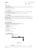
External capacitor of 47uF has to be added as near as possible from the battery connector of mother board
for charge needs.