
Installation Instruction
Ref : SCT TMO MOD SPEC 662
Rev.: B
Ref. sec. :
Date:
18/11/2004
Document
. All rights of reproduction and disclosure reserved.
MO2XX module – Confidential under NDA
Page 51/67
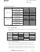
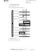
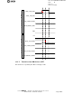
Logical and electrical levels:
Signal Logical levels Electrical levels
Active Low level
DTE_RESET*_CMD
Inactive High level
Active High level
MOD_ON_STATE
Inactive Low level
Active High level
MOD_UART_STATE
Inactive Low level
Active High level
MOD_FLOW_STATE
Inactive Low level
Active High level
MO2XX output
MOD_RESET_STATE
Inactive Low level
Active Low level
MOD_OFF*_CMD
Inactive High level
Active Low level
MOD_ON*_CMD
Inactive High level
Active Low level
DTE_UART*_STATE
Inactive High level
Active Low level
MO2XX input
MOD_RESET*_CMD
Inactive Low level
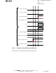
1.3.3. Communication protocols.
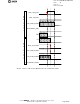
1.3.3.1. Transition tables.
This table lists the possible transition of the DCE from one state to another and which equipment can
initiate the change.
Initial Final OFF ON Sleep ON Active RESET
OFF Impossible DTE Impossible
ON Sleep DTE DCE/DTE DCE/DTE
ON Active DTE DTE/DCE DCE/DTE
RESET X Impossible X
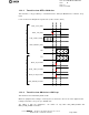
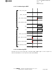
1.3.3.2. Command signals.
A logical rising edge on MOD_ON_CMD means that the DTE wants the DCE to go ON.
A logical rising edge on MOD_OFF_CMD means that the DTE wants the DCE to go OFF.
A logical falling edge on DTE_UART_STATE means that the DTE has nothing to send yet.
A logical falling edge on MOD_FLOW_STATE means that the DCE has nothing to send yet.