
Installation Instruction
Ref : SCT TMO MOD SPEC 662
Rev.: B
Ref. sec. :
Date:
18/11/2004
Document
. All rights of reproduction and disclosure reserved.
MO2XX module – Confidential under NDA
Page 33/67
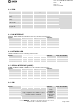
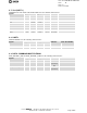
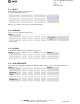
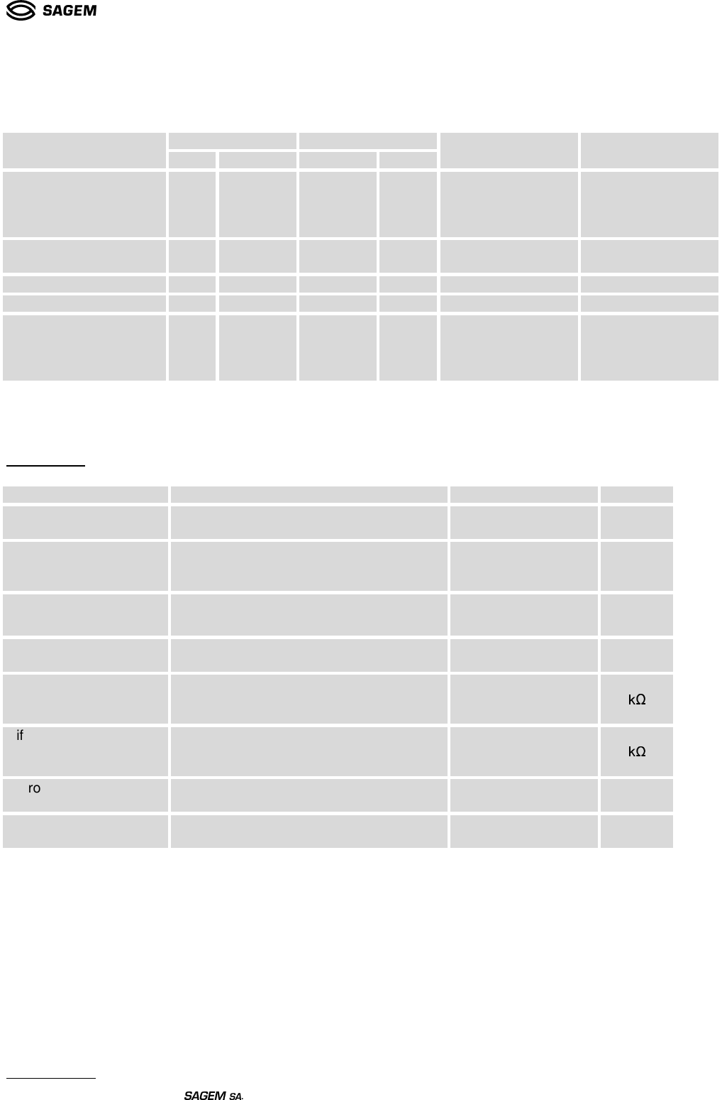
6.10 POWER MANAGEMENT
They have the following characteristics:
VL (V) VH (V)Signal
Min Max Min Max
Remarks State after RESET
MOD_RESET_STATE,
MOD_UART_STATE,
MOD_FLOW_STATE,
MOD_ON_STATE
- +0.59 +2.32 - ESD protection
PD 100K
MOD_ON*_CMD -
0.3*VBAT
0.7*VBAT
- PU
Ton min: 33 ms
DTE_UART*_STATE -0.5 +0.8 +2.03 +3.2 Prog PU
DTE_RESET*_CMD - +0.59 +2.32 -
MOD_OFF*_CMD -0.5 +0.8 +2.03 +3.2 PU
Pulse duration in
functional mode:
77ns min.
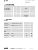
6.11 AUDIO SIGNALS
Audio Inputs
Parameter Tests Conditions Min Typ Max Units
Maximum input range
(MICIP-MICIN)
Inputs 3 dBm0 (Maximum digital sample
amplitude with PGA gain set to 0dB)
32.5 mVrms
Maximum Input Range
(HSMIC-AUXI)
Inputs 3 dBm0 (Maximum digital sample
amplitude with PGA gain set to 0dB),
HSDIF = 1
32.5 mVrms
Nominal reference level
(MICIP-MICIN)
-10 dBm0
Nominal reference level
at (HSMIC-AUXI)
HSDIF = 1 -10 dBm0
Differential input
resistance (MICIP-
MICIN)
HSDIF = 0 36
! "
Differential input
resistance (HSMIC-
AUXI)
HSDIF = 1 36
#$"
Micro amplifier gain
(MICIP- MICIN)
HSDIF = 0 25.6 dB
Micro amplifier gain
(HSMIC - AUXI)
HSDIF = 1 25.6 dB
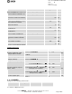
Audio Outputs