
Installation Instruction
Ref : SCT TMO MOD SPEC 662
Rev.: B
Ref. sec. :
Date:
18/11/2004
Document
. All rights of reproduction and disclosure reserved.
MO2XX module – Confidential under NDA
Page 26/67
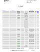
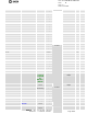
LEDG LEDG Electrical
level
output Q2 90
TSPACTEXT A_4<>
New signal
output
Radio signal
C17
67
STBYCAM A_5 <>
New signal
output standby M5 66
CSMIW2* CSMIW2 Electrical
level
Output Serial
interface for
LED chipset
Chip select for
backlight component
R3 97
CSMIW1* CSMIW1 Electrical
level
Output LCD Driver chip
select of the serial
link
S6 98
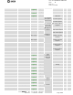
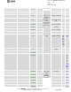
DIMIW DIMIW
Not
required
Input LCD driver input
data of serial link
T5 86
CKMIW CKMIW
Not
required
Output LCD driver clock of
serial link
S5 85
DOMIW DOMIW
Not
required
output
Serial
interface to
connect
LCD or chip
melody (1
chip select)
LCD driver output
data of serial link
S4 84
MOD_RESET*_CMD TESTRST* Electrical
level
Input
Reset system signal
P4 81
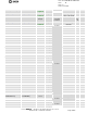
VBAT VBAT Electrical
level
Input Power
supply
+3.8V battery power
supply (nominal)
F19,
F20,
F21,
F22,
F23,
G19
,G2
0,H1
9,H2
0
Bat.
conn
.
1,2
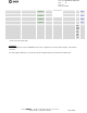
VRIO VRIO Electrical
level
Output +2.8V output power
supply
Q4 2
VBACKUP VBACKUP
Not
required
Input - P5 12
GND GND
Not
required
Ground Ground GND 8, 10,
15,
17,
48,
51,
54,
58,
60,
61, 64
Bat.
Conn
3,4
ANTENNE OUT_ANT
Not
required
Output/inp
ut
Antenna
input/output
Antenna connection
(50 ohms)
I23 Ant.
Conn.
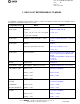
TCK TCLK
Not
required
Input JTAG
T11
Test
point
TMS TMS
Not
required
Input JTAG
T14
Test
point
TDIDIGIT TDI
Not
required
Input JTAG
C14
Test
point
TDODIGIT TDODIGIT
Not
required
Output JTAG
D17
Test
point
TDIANALOG TDIANALOG
Not
required
Input
JTAG
interface
(SAGEM
use only)
JTAG R9 Test
point