Ref : SCT TMO MOD SPEC 662 Rev.: B Ref. sec. : Date: 18/11/2004 MO2XX MODULE PRELIMINARY SPECIFICATION Document . All rights of reproduction and disclosure reserved.
Ref : SCT TMO MOD SPEC 662 Rev.: B Ref. sec. : Date: 18/11/2004 CHANGE HISTORY Rev. Date Author Reason for change A 08/09/2004 SAGEM S.A. First document B 18/11/2004 SAGEM S.A. Modifications of all § TABLE OF CONTENTS 1. OVERVIEW....................................................................................................................6 1.1 Object of the document .................................................................................................................... 6 1.
Ref : SCT TMO MOD SPEC 662 Rev.: B Ref. sec. : Date: 18/11/2004 3.8 Power management and charge .................................................................................................... 16 3.8.1 Battery ........................................................................................................................................ 16 3.8.2 VRIO........................................................................................................................................... 17 3.8.
Ref : SCT TMO MOD SPEC 662 Rev.: B Ref. sec. : Date: 18/11/2004 6.15 Clocks ............................................................................................................................................... 35 6.16 JTAG interface ................................................................................................................................. 35 7. ENVIRONMENTAL SPECIFICATION .........................................................................36 8.
Ref : SCT TMO MOD SPEC 662 Rev.: B Ref. sec. : Date: 18/11/2004 1.2.7. 1.2.8. Transition (4): Suspended Data -> Command Mode .......................................................... 66 Timeout case....................................................................................................................... 67 Document . All rights of reproduction and disclosure reserved.
Ref : SCT TMO MOD SPEC 662 Rev.: B Ref. sec. : Date: 18/11/2004 1. OVERVIEW 1.1 OBJECT OF THE DOCUMENT This document gives an overview of the MO2XX module: a miniature, single-side board, quad-band GSM/GPRS module, ready for integration in wireless communicating device as a MODEM.
Ref : SCT TMO MOD SPEC 662 Rev.: B Ref. sec. : Date: 18/11/2004 • • • • • [GSM 05.08]: "Digital cellular telecommunications system (Phase 2+); Radio subsystem link control". Version 6.8.0. [GSM 05.10]: "Digital cellular telecommunications system (Phase 2+); Radio subsystem synchronization". Version 6.6.0. AT command Set for Sagem Modules SCT TMO MOD SPEC 465 B GCF-CC (V.3.16.0) and GT.01. NAPRD.03 (V.2.10.1). 1.
Ref : SCT TMO MOD SPEC 662 Rev.: B Ref. sec.
Ref : SCT TMO MOD SPEC 662 Rev.: B Ref. sec. : Date: 18/11/2004 1.
Ref : SCT TMO MOD SPEC 662 Rev.: B Ref. sec. : Date: 18/11/2004 D.A.I UART1 interface with flow control Data/command multiplexing Power management UART2 interface Data services Supplementary services (supported via AT commands, refer to SCT TMO MOD SPEC 465 B) Reset pin Power on pin General purpose I/Os pin GPRS GSM/DCS certification GCF-CC PCS certification Document GSM DAI test mode interface Up to 115.2 Kbaud with auto bauding. Full flow control signals (+2.8V) are provided on ballout.
Ref : SCT TMO MOD SPEC 662 Rev.: B Ref. sec. : Date: 18/11/2004 2. BLOC DIAGRAM MO2xx GPRS GSM900 / GSM850*/ DCS1800 / PCS1900 VBAT Module On signal Mod_On*_Cmd Module Off signal Mod_Off*_Cmd VBAT Dte_reset*_cmd Mod_on_state Hardware Power Management Mod_uart_state Mod_Esc*._Cmd DTE_Esc.
Ref : SCT TMO MOD SPEC 662 Rev.: B Ref. sec. : Date: 18/11/2004 3. FUNCTIONAL DESCRIPTION 3.1 SIM The SIM Card interface is compatible with the ISO 7816-3 IC card standard on the issues required by the GSM 11.11 Phase 2+ standard. The module also supports Release 99 of the SIM Toolkit recommendation too and supports a Fixed Dialling Number directory.
Ref : SCT TMO MOD SPEC 662 Rev.: B Ref. sec. : Date: 18/11/2004 3.2 AUDIO The module supports the following voice codecs: • Half-Rate • Full-Rate • Enhanced Full Rate • Adaptive Multi Rate It manages an external handset microphone (MICIP/MICIN) and an external handset earphone (32 Ohms HPP32/HPN32 and 6 to 8 Ohms HPP8/HPN8) in differential mode. The bias voltage of the microphone is provided directly on MICIP/MICIN pins.
Ref : SCT TMO MOD SPEC 662 Rev.: B Ref. sec. : Date: 18/11/2004 3.3 NETWORK LED Two external pins of the module are dedicated to network and alarm LEDs: - LEDR - LEDG LEDR or LEDG Figure 4 Network LED connection 3.3.1 Network / Low BATTERY The network/battery indication consist in by a 30ms flash with period of 2 s. The flash can take 3 colors: • green when network attached and battery ok. • orange (green + red) network attached and battery low. • red no network and battery low.
Ref : SCT TMO MOD SPEC 662 Rev.: B Ref. sec. : Date: 18/11/2004 3.3.4 Summary chart Battery low : Network : + battery low : Message received : (SMS, voice / not read) + battery low : Communication : + battery low : Communication (handsfree) : + battery low : (no effect) +message: (no effect) 3.4 DATA 3.4.1 Data services The module supports the following services: • GPRS • CSD: transparent and non-transparent up to 9600 BPS • Fax: class 1 group 3 3.4.
Ref : SCT TMO MOD SPEC 662 Rev.: B Ref. sec. : Date: 18/11/2004 3.5 ANTENNA Two accesses for the antenna connection are provided. - one by mean of a 50ohms connector - one by mean of a simple copper area Antenna ground copper area Antenna copper pad 50 Ohms connector Figure 5 Antenna area on the MO2XX See into Application Note for more details. 3.6 DAI A DAI interface is provided on the module for type approval tests. 3.
Ref : SCT TMO MOD SPEC 662 Rev.: B Ref. sec. : Date: 18/11/2004 3.8.2 VRIO +2.8V output is available on external pin of the module and could supply +2.8V external components (current capability 10mA in active mode). This interface includes main protections. 3.8.3 Vbackup External Backup could be supply through the VBACKUP input (from 2.2V to 3.2V). A internal mechanism is present to charge the backup battery. If No external Backup is supplied, VBACKUP input has to be connected to VBAT signal. 3.8.
Ref : SCT TMO MOD SPEC 662 Rev.: B Ref. sec. : Date: 18/11/2004 Electric strength : reinforced insulation (EN 60950 § 5-3-2) 3.8.5.2.3 Static output template Figure 7 Is 550 mA VALID AREA 500 mA 450 mA 0 6V Charging valid area. 7V Vs 3.8.5.2.4 Dynamic output template An external device is controlling the battery charge by means of a switch S1, which can be switched on and off.
Ref : SCT TMO MOD SPEC 662 Rev.: B Ref. sec. : Date: 18/11/2004 Vs (dynamic) Is (dynamic) VALID AREA 5A Max VALID AREA 20V Max Ripple : +/- 200mV Ripple : +/- 50mA 0.2ms Max 5ms Max Time S1 is switched on Time S1 is switched off Figure 9 Transients in charge: Current transients & Voltage transients. 3.8.5.2.
Ref : SCT TMO MOD SPEC 662 Rev.: B Ref. sec. : Date: 18/11/2004 3.9 POWER MANAGEMENT 3.9.1 Interface identification and diagrams. On an external point of view (i.e. as seen by a DTE), the MO2XX has 4 different states: •OFF: In this state, none of the MO2XX functionality are running (the serial link is switched off) •ON Sleep: In this state, the MO2XX is asleep and the external serial link is switched off. Any interrupt will wake the module up as well as the external serial link.
Ref : SCT TMO MOD SPEC 662 Rev.: B Ref. sec. : Date: 18/11/2004 • The second solution consists to implement the GSM 07.10 standard, this solution is available (customer has to develop its own driver for the host). SAGEM recommends to use this solution. • A third method, developed by SAGEM S.A. and explained in details hereafter in the annex 3, consists to create a third mode for the serial link and handle it through hardware signals.
Ref : SCT TMO MOD SPEC 662 Rev.: B Ref. sec. : Date: 18/11/2004 4.
Ref : SCT TMO MOD SPEC 662 Rev.: B Ref. sec.
Ref : SCT TMO MOD SPEC 662 Rev.: B Ref. sec.
Ref : SCT TMO MOD SPEC 662 Rev.: B Ref. sec.
Ref : SCT TMO MOD SPEC 662 Rev.: B Ref. sec.
Ref : SCT TMO MOD SPEC 662 Rev.: B Ref. sec. : Date: 18/11/2004 TDOANALOG TDOANALOG BSCAN* NBSCAN EMU0* NEMU0 EMU1* NEMU1 NC Not required Not required Not required Not required Output JTAG P7 Input JTAG D16 Output For debug C18 Output For debug B18 NC Not connected Q21 ,R21 ,R20 ,S20 , L1, P3, Q6, R5, O2 * active on low electrical state WARNING: The USL signals are useless in MO2XX versions, these signals are not connected to the pins of the 120 pts connector.
Ref : SCT TMO MOD SPEC 662 Rev.: B Ref. sec. : Date: 18/11/2004 5. DELTA LIST BETWEEN MO190 TO MO2XX The MO2XX is inherited from the XS2xx. It aims to replace the MO190 module and to be compatible with it. Nevertheless, following discrepancies are noted: Compatibility issues Audio signals MO190 BFTXP/N : st 1 gain : [-12, -6, 0, +6, +12, +18, +21] dB MO2XX HSMICIP/N : Only 25.6 dB (see § 6.11.2) nd 2 gain : 4.6 or 28.
Ref : SCT TMO MOD SPEC 662 Rev.: B Ref. sec. : Date: 18/11/2004 LEDG Imax = 4 mA Electrical level : to be verified LEDR Imax = 4 mA Electrical level : to be verified VBAT Vmax = 5V Electrical limitation : Vmax = 4.5V V56 available Hardware incompatibility : not available VRIO Current capability sleep mode = 1 mA Electrical limitation : Current capability sleep mode = 0.5 mA ADC2 ADC1 Hardware interfacing : 5.
Ref : SCT TMO MOD SPEC 662 Rev.: B Ref. sec. : Date: 18/11/2004 6. ELECTRICAL SPECIFICATION VOH VOL VIH VIL High level output voltage Low level output voltage High level input voltage Low level input voltage 6.1 VBAT The module is supplied through the VBAT signal with the following characteristics: Parameter Name Min Typ Max VBAT period (ms) VbatTe (*) 4.614 4.
Ref : SCT TMO MOD SPEC 662 Rev.: B Ref. sec. : Date: 18/11/2004 6.2 VRIO Signal Voltage level (activ mode) Voltage level (sleep mode) Current capability Active mode Current capability Sleep mode Rise time Min Typ Max 2.70V 2.80V 2.90V 2.70V 2.80V 3.00V - - 10mA - - 0.5mA - 10µs - Remarks 6.3 DAI INTERFACE DAIRST, DAIIN, DAICLK and DAIOUT have the following characteristics: Signal VL (V) VH (V) Remarks Min Max Min Max DAIRST -0.5 +0.8 +2.03 +3.2 DAICLK -0.5 +0.8 +2.03 +3.
Ref : SCT TMO MOD SPEC 662 Rev.: B Ref. sec. : Date: 18/11/2004 6.7 V24 (UART 1) TXD,RXD,CTS, RTS, DCD, DSR, DTR and RI have the following characteristics: Signal VL (V) VH (V) Remarks State after reset Min Max Min Max RTS -0.5 +0.8 +2.03 +3.2 PU 100K RI +0.59 +2.32 CTS +0.59 +2.32 DSR +0.59 +2.32 PD DCD +0.59 +2.32 PU 10K DTR -0.5 +0.8 +2.03 +3.2 PU 100K TXD1 +0.59 +2.32 RXD1 -0.5 +0.8 +2.03 +3.2 PU 10K 6.8 UART2 TXD2 and RXD2 have the following characteristics: Signal VL (V) VH (V) Min Max Min RXD2 -0.
Ref : SCT TMO MOD SPEC 662 Rev.: B Ref. sec. : Date: 18/11/2004 6.10 POWER MANAGEMENT They have the following characteristics: Signal VL (V) Min Max MOD_RESET_STATE, +0.59 MOD_UART_STATE, MOD_FLOW_STATE, MOD_ON_STATE MOD_ON*_CMD 0.3*VBAT DTE_UART*_STATE DTE_RESET*_CMD MOD_OFF*_CMD -0.5 -0.5 +0.8 +0.59 +0.8 VH (V) Min +2.32 Remarks Max - 0.7*VBAT - +2.03 +2.32 +2.03 +3.2 +3.2 State after RESET ESD protection PD 100K PU Ton min: 33 ms Prog PU PU Pulse duration in functional mode: 77ns min. 6.
Ref : SCT TMO MOD SPEC 662 Rev.: B Ref. sec. : Date: 18/11/2004 Parameter Tests Conditions Differential Minimum resistive load between HPP32 and HPN32 ; R// Min Typ Max Units Output swing 3.9 Vpp 120 & Output swing 1.
Ref : SCT TMO MOD SPEC 662 Rev.: B Ref. sec. : Date: 18/11/2004 6.13 RESET MOD_RESET*_CMD is active at low state It has the following characteristics: Signal Min VL (V) VH (V) Treset (ms) 0.7 VBAT 65 Max Remarks 0.3 VBAT - Electrical levels TBC NB: The reset signal resets all the system including backup. 6.14 SPARE IO IO5, 6, 7 have the following characteristics: Signal VL (V) VH (V) Min Max Min Input -0.5 +0.8 +2.03 Output +0.59 +2.32 Iout max = 2mA Remarks Max +3.
Ref : SCT TMO MOD SPEC 662 Rev.: B Ref. sec. : Date: 18/11/2004 7.
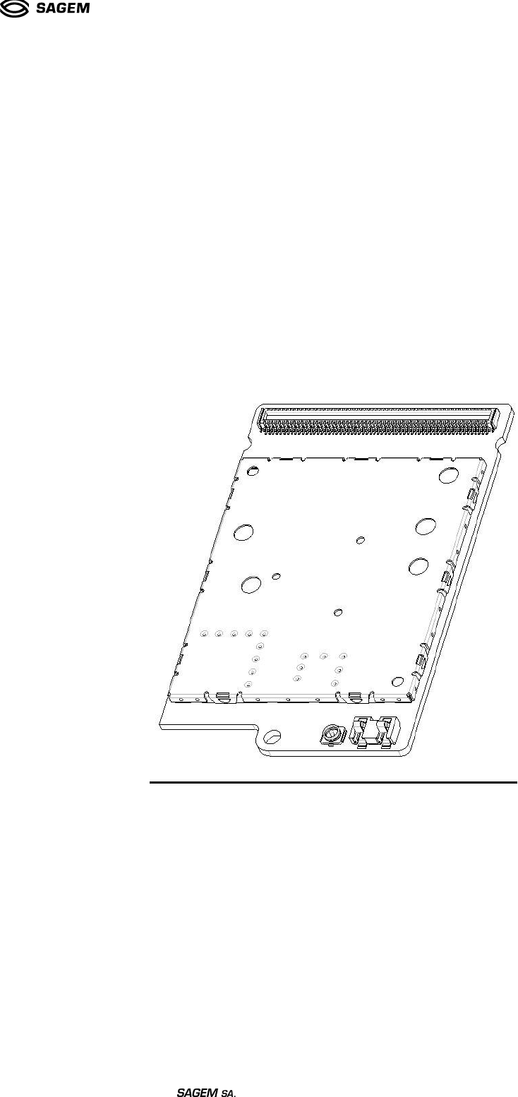
Ref : SCT TMO MOD SPEC 662 Rev.: B Ref. sec. : Date: 18/11/2004 8. MECHANICAL SPECIFICATION 8.1 PHYSICAL DIMENSIONS AVX Board to Board connector 60 1 61 120 JST 2 way stacker assembly Ground area Pad for antenna connection Murata coaxial connection Figure 10 MO2XX Document . All rights of reproduction and disclosure reserved.
Ref : SCT TMO MOD SPEC 662 Rev.: B Ref. sec. : Date: 18/11/2004 Figure 11 MO2XX dimensions . All rights of reproduction and disclosure reserved.
Ref : SCT TMO MOD SPEC 662 Rev.: B Ref. sec. : Date: 18/11/2004 Figure 12 MO2XX connection to a mother board . All rights of reproduction and disclosure reserved.
Ref : SCT TMO MOD SPEC 662 Rev.: B Ref. sec. : Date: 18/11/2004 8.2 TERMINAL ASSIGNMENTS 8.2.1. 120 PINS CONNECTOR 8.2.1.1. MO2XX connector Recommended PC Board Mounting pattern: Dimensions and references: Pin Number Reference 120 AVX 10 5604 120 212 829 Document . All rights of reproduction and disclosure reserved.
Ref : SCT TMO MOD SPEC 662 Rev.: B Ref. sec. : Date: 18/11/2004 8.2.1.2. Mother board connector Recommended PC Board Mounting pattern: Dimensions and references: Pin Number References 120 AVX 20 5604 120 222 829 Document . All rights of reproduction and disclosure reserved.
Ref : SCT TMO MOD SPEC 662 Rev.: B Ref. sec. : Date: 18/11/2004 8.2.2. MO2XX ANTENNA CONNECTOR Document . All rights of reproduction and disclosure reserved.
Ref : SCT TMO MOD SPEC 662 Rev.: B Ref. sec. : Date: 18/11/2004 8.2.3. BATTERY CONNECTOR Document . All rights of reproduction and disclosure reserved.
Ref : SCT TMO MOD SPEC 662 Rev.: B Ref. sec.
Ref : SCT TMO MOD SPEC 662 Rev.: B Ref. sec.
Ref : SCT TMO MOD SPEC 662 Rev.: B Ref. sec.
Ref : SCT TMO MOD SPEC 662 Rev.: B Ref. sec.
Ref : SCT TMO MOD SPEC 662 Rev.: B Ref. sec. : Date: 18/11/2004 ANNEX 2 : Hardware power management Different strategies The transition of the MO2XX from awake to asleep can be managed in 4 different ways: • Inhibition by DTE: The DTE can forbid the MO2XX to go to sleep. But if it is allowed to sleep, it do it when it wants and without informing the DTE. This allows a very simple management by the DTE but should be used when the power management is not a critical issue.
Ref : SCT TMO MOD SPEC 662 Rev.: B Ref. sec. : Date: 18/11/2004 When the UART of the MO2XX doesn't detect any activity on the RX input during a certain time, it allows the MO2XX to switch off the UART when it wants. The DTE doesn't know when the MO2XX switches its UART off. If the DTE sends data to the MO2XX when the UART is off, the first character will wake up the DCE and the first byte may be lost. Another way for the DTE to wake up the MO2XX is to put down its DTR or RTS. 1.2 Inhibition by DTE.
Ref : SCT TMO MOD SPEC 662 Rev.: B Ref. sec. : Date: 18/11/2004 MOD_FLOW_STATE is inactive when the MO2XX has nothing to send. MOD_RESET_STATE is active during the the software reset procedure, but it can not be trusted during hardware reset. MOD_OFF*_CMD command the switch off of the MO2XX. MOD_ON*_CMD command the switch on of the MO2XX. DTE_UART*_STATE is inactive when the DTE has nothing to send. If MOD_FLOW_STATE is inactive too, the DTE can switch off its UART.
Ref : SCT TMO MOD SPEC 662 Rev.: B Ref. sec.
Ref : SCT TMO MOD SPEC 662 Rev.: B Ref. sec. : Date: 18/11/2004 1.3.3.3. Transition from OFF to ON Active. This transition is only possible by a command from the DTE (the MO2XX never switches off by itself). Levels shown on the diagram are logical levels (active, inactive, either) MOD_OFF_CMD D C E MOD_ON_CMD i n p u t s DTE_UART_STATE MOD_RESET_CMD RX TX D C E MOD_ON_STATE o u t p u t s MOD_UART_STATE MOD_FLOW_STATE MOD_RESET_STATE 1.3.3.4. Transition from ON Active to ON Sleep.
Ref : SCT TMO MOD SPEC 662 Rev.: B Ref. sec. : Date: 18/11/2004 1.3.3.4.1. Initiated by DTE. MOD_OFF_CMD D C E i n p u t s MOD_ON_CMD UART is OFF DTE_UART_STATE MOD_RESET_CMD RX TX D C E o u t p u t s MOD_ON_STATE MOD_UART_STATE MOD_FLOW_STATE MOD_RESET_STATE state 1 state 2 This transition show 2 transitory states. During transitory states 1 and 2, the DTE can't send data. If it has to, it must put DTE_UART_STATE up first.
Ref : SCT TMO MOD SPEC 662 Rev.: B Ref. sec. : Date: 18/11/2004 1.3.3.4.2. Initiated by DCE. MOD_OFF_CMD D C E i n p u t s MOD_ON_CMD UART is OFF DTE_UART_STATE MOD_RESET_CMD RX TX D C E o u t p u t s MOD_ON_STATE MOD_UART_STATE MOD_FLOW_STATE MOD_RESET_STATE state 3 state 2 This transition show 2 transitory states. During transitory states 2 and 3, the DCE can't send data: • If it has to during state 2 it must put MOD_FLOW_STATE up (cf. 2.2.3.3.4.3.a) to wake up the DTE.
Ref : SCT TMO MOD SPEC 662 Rev.: B Ref. sec. : Date: 18/11/2004 1.3.3.4.3. Transitory states. a) DTE has data to send: This case can happen in transitory state 1 and state 2. MOD_OFF_CMD D C E i n p u t s MOD_ON_CMD DTE_UART_STATE MOD_RESET_CMD RX TX D C E o u t p u t s MOD_ON_STATE MOD_UART_STATE MOD_FLOW_STATE MOD_RESET_STATE b) DCE has data to send: This case can happen in transitory state 2. Document . All rights of reproduction and disclosure reserved.
Ref : SCT TMO MOD SPEC 662 Rev.: B Ref. sec. : Date: 18/11/2004 MOD_OFF_CMD D C E MOD_ON_CMD i n p u t s DTE_UART_STATE MOD_RESET_CMD RX TX D C E MOD_ON_STATE o u t p u t s MOD_UART_STATE MOD_FLOW_STATE MOD_RESET_STATE 1.3.3.5. Transition from ON Sleep to ON Active. This transition can be initiated by both the DTE and the DCE. Document . All rights of reproduction and disclosure reserved.
Ref : SCT TMO MOD SPEC 662 Rev.: B Ref. sec. : Date: 18/11/2004 1.3.3.5.1. Initiated by the DCE. MOD_OFF_CMD D C E i n p u t s MOD_ON_CMD DTE_UART_STATE MOD_RESET_CMD RX TX D C E o u t p u t s MOD_ON_STATE MOD_UART_STATE MOD_FLOW_STATE MOD_RESET_STATE 1.3.3.5.2. Initiated by DTE. The DCE can react on the rising edge of the DTE_UART_STATE signal or on the reception of a character which will be lost. It is only used to wake up the MO2XX. Document ¡ .
Ref : SCT TMO MOD SPEC 662 Rev.: B Ref. sec. : Date: 18/11/2004 MOD_OFF_CMD D C E MOD_ON_CMD i n p u t s DTE_UART_STATE MOD_RESET_CMD This character is not mandatory and will be lost RX TX D C E o u t p u t s MOD_ON_STATE MOD_UART_STATE MOD_FLOW_STATE MOD_RESET_STATE 1.3.3.6. Transition from ON Sleep to OFF. This transition is only possible by a command from the DTE (the MO2XX never switches off by itself). Document ¢ . All rights of reproduction and disclosure reserved.
Ref : SCT TMO MOD SPEC 662 Rev.: B Ref. sec. : Date: 18/11/2004 MOD_OFF_CMD D C E i n p u t s MOD_ON_CMD DTE_UART_STATE MOD_RESET_CMD RX TX D C E o u t p u t s MOD_ON_STATE MOD_UART_STATE MOD_FLOW_STATE MOD_RESET_STATE 1.3.3.7. Transition from ON Active to OFF. This transition is very unlikely but still theoretically possible. Document £ . All rights of reproduction and disclosure reserved.
Ref : SCT TMO MOD SPEC 662 Rev.: B Ref. sec. : Date: 18/11/2004 MOD_OFF_CMD D C E i n p u t s MOD_ON_CMD DTE_UART_STATE MOD_RESET_CMD RX TX D C E o u t p u t s MOD_ON_STATE MOD_UART_STATE MOD_FLOW_STATE MOD_RESET_STATE Another solution to switch off the MO2XX is the AT command AT+CPOF: Document ¤ . All rights of reproduction and disclosure reserved.
Ref : SCT TMO MOD SPEC 662 Rev.: B Ref. sec. : Date: 18/11/2004 MOD_OFF_CMD D C E MOD_ON_CMD i n p u t s DTE_UART_STATE MOD_RESET_CMD RX TX D C E AT+CPOF OK MOD_ON_STATE o u t p u t s MOD_UART_STATE MOD_FLOW_STATE MOD_RESET_STATE 1.3.3.8. Reset There are 2 possibilities : • The MO2XX reboots by itself for a major internal problem and warns the DTE of this operation. In this case, the MO2XX moves the MOD_RESET_STATE signal to Active.
Ref : SCT TMO MOD SPEC 662 Rev.: B Ref. sec. : Date: 18/11/2004 1.3.3.8.1. Initiated by the DCE. RESET ON MOD_OFF_CMD D C E i n p u t s MOD_ON_CMD DTE_UART_STATE MOD_RESET_CMD RX TX D C E o u t p u t s MOD_ON_STATE MOD_UART_STATE MOD_FLOW_STATE MOD_RESET_STATE Document ¦ . All rights of reproduction and disclosure reserved.
Ref : SCT TMO MOD SPEC 662 Rev.: B Ref. sec. : Date: 18/11/2004 1.3.3.8.2. Initiated by the DTE. RESET ON MOD_OFF_CMD D C E i n p u t s MOD_ON_CMD DTE_UART_STATE MOD_RESET_CMD RX TX D C E o u t p u t s MOD_ON_STATE MOD_UART_STATE MOD_FLOW_STATE MOD_RESET_STATE 1.3.3.9. Timeout. If a command has no effect on the other equipment, it must be requested again after a one second timeout. The maximum number of requests is 5 and then a reset procedure of the DCE must be initiated by the DTE.
Ref : SCT TMO MOD SPEC 662 Rev.: B Ref. sec. : Date: 18/11/2004 ANNEX 3 : Data/Command hardware multiplexing 1. Hardware multiplexing 1.1. External interfaces In the first set (hardware MUX), we need to use two hardware signals (MOD_ESCAPE*_CMD and DTE_ESCAPE_CMD) and the full serial link V24. In the second set, we only need to use the full V24. To make an interface with a host, the MO2xx hardware multiplexing signals need no added hardware. 1.2. Capability requirements 1.2.1.
Ref : SCT TMO MOD SPEC 662 Rev.: B Ref. sec. : Date: 18/11/2004 1.2.3. State diagram Already implemented To be defined DTE : +++ COMMAND 1 DATA DTE : ATO DTE : ATO 4 3 2 DTE : ATH OU Modem : NO CARRIER DTE : MOD_ESCAPE*_CMD OR Modem : DTE_ESCAPE_CMD SUSPENDED DATA 1.2.4. Transition (1): Command -> Data The data connection is established when the PDA receives the “CONNECT: ” message from the SB.
Ref : SCT TMO MOD SPEC 662 Rev.: B Ref. sec. : Date: 18/11/2004 Remarks: • DTE_ESCAPE_CMD = MOD_ESCAPE_CMD = {0x18,0x7E,0xDB,0xFF}, this string could be change by AT command in the future. • These two strings are the effective separation between the data flow and the command flow nd 2 case: the modem requests the DTE to go in the suspended data mode 1. The modem indicates the request by moving DTE_ESCAPE_CMD. 2.
Ref : SCT TMO MOD SPEC 662 Rev.: B Ref. sec. : Date: 18/11/2004 Suspended data mode COMMAND DTE Tx ATH COMMAND COMMAND Modem Tx Command mode OK COMMAND 1.2.8. Timeout case If modem didn’t receive the DTE_ESCAPE_STR after a timeout (2s), it send again his MOD_ESCAPE_STR and wait for DTE_ESCAPE_STR as long as the MOD_ESCAPE*_CMD signal is active. After 3 retry, module closes the MUX mechanism.