
User's Manual

s
e
Centre de Saint Christophe - URD 37
TELEPHONIE MOBILE
MOBILE PHONES
Ref. : SCT TMO MASV2 SPEC 14 M
Date : 04/03/03
E All rights reserved. Reproduction and disclosure prohibited Page 12
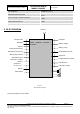
MO130 module for mobile applications
This document contains information on a product under development. SAGEM reserves the right to change or discontinue this product
without notice.
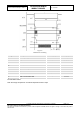
Figure 4
Serial link timing
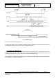
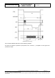
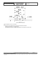
Figure 5
Reset serial link timing
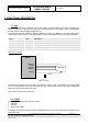
This interface includes main protections.
If another LCD driver is used, the software would be provided by SAGEM, or at least the specific drivers will
be integrated by SAGEM. In that case a specific quotation is required.
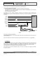
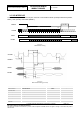
3.4 PARALLEL INTERFACE
A parallel interface is provided on the 120 pins connector. This interface include 16 bits data lines (D<0..15),
7 address lines (A<0>,A<1>, A<2>, A<3>, A<4>, A<5>,A<6>), Write control signal RW* (active low), Output
Enable signal OE* (active low) and two chip selects CS2 and CS3 (active low).
NB: The maximum capacitance acceptable on each signal of the parallel interface is 25pF (including copper
line capacitance, connectors capacitance…).
> 1µs
RESETLCD∗
Software initialisation