
User's Manual

s
e
Centre de Saint Christophe - URD 37
TELEPHONIE MOBILE
MOBILE PHONES
Ref. : SCT TMO MASV2 SPEC 14 M
Date : 04/03/03
E All rights reserved. Reproduction and disclosure prohibited Page 11
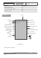
MO130 module for mobile applications
This document contains information on a product under development. SAGEM reserves the right to change or discontinue this product
without notice.
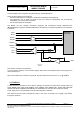
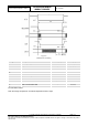
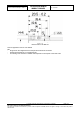
The bias voltage of the microphone is provided directly on MICP/MICN pins.
There are three options for the earphone:
- One multi-mode earphone, as earpiece, hands free loudspeaker and melody/ring.
- Two earphones, one 32 Ohms as earpiece and one 8 Ohms as Ring/melody and as hands-free
loudspeaker if it is far from the microphone.
- one 32 Ohms earphone as earpiece.
The Module can also manage accessories (earphone and microphone) through dedicated lines
(BFRXP/BFRXN for earphone and BFTXP/BFTXN for microphone). The typical impedance for the earphone
is 150ohms.
Figure 3
Audio
This interface includes main protections.
To ensure proper operation of such sensitive signals, there have to be isolated from the other by ground on
mother board layout.
NB: To avoid destruction of module components, the HP inductance has to be 47nH +/- 5% @ 200MHz
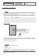
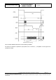
3.3 DISPLAY
A serial interface is provided on the module to manage an external LCD (256 colour) through data input
signal (DIMIW), data output signal (DOMIW), clock (CKMIW), reset (RESETLCD*), register select (RSLCD)
and two chip selects (CSMIW1 and CSMIW2), one dedicated to the LCD, the other to the chip melody.
Power supply of the LCD (ALIMLCD) is also provided through this interface.
This interface could be used to manage two LCDs. In this case, the module can’t manage a chip melody
through this serial link.
Base-band
Ampli+Filter
MICP
MICN
BFTXP
BFTXN
HPIN
BFRXP
BFRXN
HPP
HPN
LPHP