Reference number : 4618 - 007 STANDARD SERIES METALDETECTORS INSTRUCTION MANUAL FIRMWARE 2.01 TO 2.
Copyright © Safeline limited, 1990, 1997, 1998 No part of this document may be reproduced, or translated, in any form, electronic or otherwise without the prior written consent of Safeline limited. Neither Safeline nor its Agents will be liable for incidental or consequential damage in connection with the use of this document. Safeline reserve the right to change the contents or form of this manual at any time without prior notice having been given.
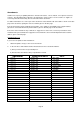
Amendments Safeline have a policy of updating manuals to include new features, correct erratum, or incorporate customers requests. The Amendment Record below is provided for the express purpose of the customer, or supplier, to record any amendments that may have been included in this document. For further information or to order copies of this document contact Safeline Ltd. at the address shown on the title page of this document, quoting the reference number given on the title page.
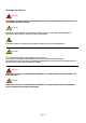
Warnings and Cautions WARNING THE ABOVE CAPTION IDENTIFIES AN OPERATING PROCEDURE OR PRACTICE THAT COULD RESULT IN PERSONAL INJURY OR DEATH. ! CAUTION The above caption identifies an operating procedure or practice that could result in damage, or destruction, of the detector, the process or its surroundings. The above caption is used to draw the readers attention to a note of extra importance. ! CAUTION This manual is regarded as an integral part of the detector.
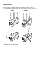
Handling instructions The detector does not contain any exposed noxious or dangerous substances. When transporting and handling the detector damage may result if the lifting equipment (i.e. sling, cable assembly or by hand) passes through the aperture of the detector. The diagrams below show the incorrect way and the correct way to lift and support the detector during transportation. CORRECT INCORRECT Safeline does not recommend the lifting or supporting of the detector by a person.
Safety Instructions Most companies have a code of practice for their employees which is designed to ensure their safety in the working environment. When new equipment is introduced it is important that operators, maintenance engineers and supervisors are aware of the potential hazards. The following guidelines must be followed by any person concerned with the operation, installation or handling of the detector to ensure correct operation and to avoid any damage to the detector or to the person concerned.
Detector Precautions ! CAUTION During installation and operation of the detector the following points must be considered. Failure to do so may result in difficulties of operation, degradation in the performance or damage occurring to your detector. 1. Electric Arc Welding Electric Arc Welding must not be carried out on the detector or on any part of the attached conveyor system.
6. Avoiding aperture damage At all times ensure that the product does not come in contact with, or impact onto the detector aperture or aperture lining. 7. Handling and lifting When transporting and handling the detector damage may result if the lifting equipment (e.g. sling, cable assembly or by hand) passes through the aperture of the detector. Never pass any lifting or supporting equipment through the detector aperture.
CONTENTS PRELIMINARY PAGES Aims of this manual. ...................................................................................................................................................... ii Amendments..................................................................................................................................................................iii Warnings and Cautions ................................................................................................................
LIST OF ILLUSTRATIONS Figure 1 2 3 4 5 6A 6B 6C 7 8 9 10 11 Page Vector diagram................................................................................................................................. Detector coil system signals ............................................................................................................ Effect of phase control .....................................................................................................................
THIS MANUAL INCLUDES ALL THE FEATURES AVAILABLE WITH THE FIRMWARE VERSION 2.01 to 2.49 PLEASE NOTE THAT ALL THESE FEATURES MAY NOT BE INCLUDED AS STANDARD. NOTICE The information contained in this document is subject to change without notice. All efforts have been made to ensure the accuracy of this manual. However, should any error be detected, Safeline would greatly appreciate being informed of them.
SPECIFICATION - STANDARD SERIES DETECTORS Product speed BASIC TECHNOLOGY Selectable high and low from the control panel, low - x 1, high - x 3 High frequency low power electromagnetic coil system. Low - 0.05 to 2.5 metres / min. / mm. of aperture height (4 to 200 feet / min. / inch of aperture height) Frequency of Operation Crystal controlled in the range 10 kHz to 500kHz staggered frequency versions available. High - 0.05 to 7.5 metres / min. / mm of aperture height (12 to 600 feet / min.
Spherical Sensitivity RS232 Communication Dependent on aperture size, and frequency of operation, all sensitivity information is expressed in diameters of spherical samples. Two communication ports COM1 and COM2 both accessible from the P/S Connection PCB within the Power Unit Enclosure. Non spherical objects such as wires will exhibit an orientation effect, ie. they can be more easily detected in certain axis.
BASICS ABOUT METALDETECTORS Vibration signals can be represented in the same way as signals, generated by metal particles. ie a vector with amplitude and phase. Basic Principles of Operation Safeline detectors utilise a low power high frequency magnetic field coil system which has the ability to sense minute disturbance created by metal particles. A metal particle passing through the aperture of the detector will create changes in the magnetic field inside the detector.
A comparison can be made with a commercial/domestic Hi-Fi system. The volume control of the Hi-Fi increases/decreases the amplitude of all signals just like the metal detector sensitivity control. The bass control of the Hi-Fi selectively controls the low frequency notes only. This is similar to the phase discrimination circuit, however the phase discrimination circuit in the Safeline metal detector is very much more selective. Signals from the detector coil system can also be represented as shown in Fig 2.
INSTALLATION GENERAL It is the effect of the leakage magnetic field on the surrounding metalwork that may influence the detectors performance and can give rise to spasmodic detection signals and inconsistent performance. Safeline advise users to carefully study the installation advice provided; a little care taken during installation will avoid the detectors performance from being severely impaired.
Magnetic Loops The design and Construction of the metal detector support framework can be very influential on the overall performance of the detector. A metal detector with excellent vibration characteristics, if mounted on a structure containing magnetic loops can be made to look extremely poor and very sensitive to vibration.
connections and the position and rating of the recommended circuit breaker are shown in Fig. 6B. These instructions are for connection to TN (EN60950:1992) power distribution systems only. For connections to other power distribution systems please contact your supplier. Arrangement of the gland assemblies for connecting the power cable to the power unit box are shown in Fig. 6C. An information booklet is available with more detailed Guidelines regarding metal detection conveyor design.
1 45 46 47 48 49 50 51 52 53 54 55 56 FUSE F1: 3.15A (T) (ON POWER SUPPLY MODULE UNDERNEATH THE CONNECTIONS BOARD) NOT A USER SERVICABLE PART 2 3 4 5 6 7 8 29 30 31 32 33 34 35 36 37 38 39 40 41 42 43 44 9 10 11 12 13 14 15 16 17 18 Layer 1 20 21 22 23 24 25 26 27 28 19 OPTIONAL REJECT CONFIRMATION UNIT CIRCUIT BOARD 57 58 59 60 61 62 63 64 65 FUSE: F2: 1.
RATINGS 1) RECOMMENDED POWER LEAD 2 AREA 0.75 mm CONSTRUCTION 24 x 0.2 mm CURRENT RATING 6 AMP. COLOURS BROWN-LIVE, BLUE-NEUTRAL, GREEN/YELLOW-EARTH. 2) a) RECOMMENDED CIRCUIT BREAKER DOUBLE POLE, CURRENT RATING 3 AMP OR 4 AMP, TYPE C CIRCUIT BREAKER TO BE MOUNTED CLOSE TO EQUIPMENT. OR b) RECOMMENDED FUSE RATING CURRENT RATING 4 AMP OR 5 AMP ANTI-SURGE (T).
Figure 6C Cable Gland Assemblies for Power Supply Unit Page 9A
Figure 7 Roller Shaft Insulation (one end only) Figure 8 Bearing Block Insulation Page 9B
THIS PAGE IS LEFT BLANK INTENTIONALLY Page 9C
Page 10
THE CONTROL PANEL Introduction on the LCD display but not altered. The metal detector control panel (see Fig 11) is the interface by which the user may observe and control the metal detectors performance. All of the metal detectors operating characteristics may be programed through the control panel. A Liquid Crystal Display ’LCD’ shows the information contained in the metal detectors computer, with this display and by use of the touch keys the metal detectors performance is controlled.
OPERATING AND ACCESS MODES THE DISPLAY AND TOUCH KEY FUNCTIONS Running Mode Liquid Crystal Display (LCD) This represents the normal running display of the metal detector. In this mode information may be observed but the display values cannot be changed. Used to display the information in the metal detector’s computer. Bar Graph Display Displays the level/amplitude of signals generated in the detector head. If green the signal is below the level required to trigger the metal detector.
THE PAGE DISPLAY SYSTEM OPERATING AND ACCESS MODES - Continued There is a requirement to display more informa- tion than the LCD can display at any one time. To expand the display capabilities a page display menu system is used. This can be compared to the pages of a book. When there is more than one page of information to be displayed an etc prompt will appear on the display. Pressing the appropriate ’soft key’ adjacent to ’etc’ will cause the display to move to the next page or scroll forward.
ENTERING THE ACCESS CODES USING THE TOUCH KEYS Cursor Move Key All Safeline metal detectors are shipped from the factory with the following access codes. Code 0001 = Operator Access This key is used to control the movement of the cursor bar when changing the setting of a digital value. A small cursor bar will appear under the active digit on the LCD display when a parameter is available for adjustment Example 1 2 3 4 one press of the cursor move cursor bar one step to the left.
CHANGING DIGITAL VALUES PROGRAMMABLE SETTINGS Various settings in the progamme are stored as digital values, eg product number, sensitivity, phase etc. Digital values can only be adjusted if a pointer > is visible on the LCD display adjacent to the parameter to be adjusted and pointing toward the appropriate soft key. General Twenty one presettable programmes can be stored in the computers memory. Each programme is identified by a product number.
PROGRAMMABLE SETTlNGS – continued Inverse Detection (Inverse Detect Yes/No) This feature allows the action of the reject timer to be reversed, such that product containing no metal contamination is rejected whilst metal contaminated product is not rejected. This feature is often used to verify that a product contains a metallic premium. NB:– This feature can only be selected when using a gated timer.
CONFIGURING THE DETECTOR Various operating characteristics of the detector are programmable and may be altered or configured to suit the particular requirements of the application. The configuration process should be performed by the engineer when first installing the detector. DETECTOR SPEED Hi/Lo - select to suit product throughput speed. See specification for speed range. Will normally be set to Lo for most conveyor applications and Hi for free fall applications.
SET TIME - Firmware 2.21 or less Allows the setting of HOUR and MINUTE. The clock uses the 24 hour format. Refer to ’Changing Digital Values’ for adjustment. PRINTER HANDSHAKE - Firmware 2.10 or greater HW/SW controls the handshaking mode the Module uses with Local Printer Unit (LPU). If software (SW) handshake is selected the Module uses X-ON and X-OFF flow control. Normally set to hardware (HW) handshake.
REJECT TIMERS – GENERAL TlMER TYPES A wide range of timer types and settings are available to the engineer. Five different timer types, each with variable settings can be pro- grammed for use within the metal detector. The types are as follows: the reject solenoid, and the reject mechanism may need to be taken into account. RECOMMENDED APPLICATIONS Listed below are various types of reject mechanisms encountered in detection applications with recommended timer types for fixed speed applications.
tm1 – TIMER 6) Enter required value The tm1 reject timer is useful for applications requiring instantaneous reject action with zero delay time. Typical applications would be gravity fall reject mechanism or simple stop alarm conveyor system. 7) Press enter twice: display reads: Timer A,B,C Type tm1 SET/UPDATED for five seconds and then returns to main menu Sample Size Small size metal contaminants should be used to set the timer, the use of large contaminants will produce errors in the settings.
tm2[G] TIMER – NON GATED MODE The tm2[G] timer used in the non-gated mode is an ideal delayed reject timer for use with loose product where the reject device is a reasonable distance from the detector head. It can also be used with individual products where precise reject operation is not crucial. When setting up the timer there are some basic rules that must be applied. device to reject contaminated product. The mini- mum value will be the operate time of the reject device.
8) Select ’No’, display now reads: Signal Delay # # # #sec Reject Time # # # #sec tests using larger metal samples. If product is loose test reject operation using large and small samples, also check using two metal samples spaced at different distances apart on belt.
tm2[G] TIMER – GATED MODE Sync Delay The tm2(G) photogated reject timer gives precise operation of the reject device where individual products, eg cartoned products, individual chocolate bars etc are transported on a conveyor. Photogating ensures that the reject operation is independent of the position of metal contamination within the product. Sync delay is the time taken for the pack to travel from the photo beam to the optimum reject position.
such that the pack/product breaks the beam before reaching the reject device. The beam may be positioned either side of the detector. Ensure the sensors do not effect the operation of the metal detector itself by infringing the metal free zone limitations. At line speeds of 61m/min (200ft/min) or greater the sensors must not be positioned too close to the reject device, ensure a minimum distance of 0.5m (1.5ft).
b) A metal test piece is not required to set these two parameters the front or rear edge on the conveyor belt and allow it to pass through the detector without skewing or slippage. Press the ’Reject Time’ soft key and adjust the reject time until the metal contaminated pack is cleanly rejected. 13) Ensure that the photo beam(s) is/are clear of obstructions and press the ’window time’ soft key. The display will read ’Cal’ for 5 seconds then ’ ‘Run’.
tm3[G] TIMER The tm3[G] is a variable speed version of the tm2[G) timer, Setting Up Timer Type tm3[G] – Non Gated Mode The tm2[G] timer has four time clock controlled functions that will provide an accurate reject action on a fixed speed conveyor. To set up the timer use the following procedure: The tm3[G] timer has three of these functions controlled by a speed sensor attached to the conveyor, which enables an accurate ”reject action to be maintained over a wide range of speeds.
8) Select ’No’ display now reads Setting Up Timer Type tm3[G] – Gated Mode Signal Shift # # # To set up the timer use the following procedure: Reject Shift # # # 1) Prepare a sample pack containing a small metal contaminant positioned at the rear/trailing edge. 9) 2) Enter the Engineers access code For loose product use the smallest metal test piece positioned on the belt, for packaged products use the smallest metal test piece positioned at the rear/trailing edge of the pack.
keys such that the reject mechanism operates just as the front/leading edge of the pack reaches the centre of the reject device. When set – press ENTER once 10) The reject shift will be adjusted as the last operation so do not worry at this stage about the reject mechanism operation. Shows CAL for 5 seconds after which ‘RUN’ Appears.
When a satisfactory setting has been achieved. Press ENTER once. The Reject Time should now be adjusted. 14) Press the ’Etc’ soft key the display now reads Signal Shift 4## Reject Time ####sec Etc Place the sample pack with metal contaminant in the front or rear edge on the conveyor belt and allow it to pass through the detector without skewing or slippage. Press the ’Reject Shift’ soft key and adjust the reject time until the metal contaminated pack is cleanly rejected.
PROGRAMING THE DETECTOR GENERAL At this stage the metal detector should have been installed and configured and the user be familiar with the basic operation of the control panel as described in previous sections. The Safeline detector has the ability to store settings for 21 different product numbers. Each product number represents a group of settings, the appropriate setting of sensitivity, phase, timer type and inverse detection may be allocated to each product number.
signal of 2 to 3 green segments on the bar graph display. PRODUCT EFFECT APPLICATIONS 6) Test the detection sensitivity with metal samples. Wet/moist product, ie meat, cheese, soups etc generate product signals when passed through the detector. At setting Phase 0000 the signal will be clearly visible on the LED Bar graph display. Minimising Product Effect Signal By Manually Adjusting The Phase Discriminator. With this type of product there are two alternative settings for the detector.
2) Enter access code. phase setting up and down until minimum signal ie. the null point is found. 3) Select lowest available product number (01 to 20). 11) The phase discriminator is now aligned to the product signal, next adjust the sensitivity so that the product signal gives a maximum signal of 2 to 3 green bars on the bar graph display. 4) Manually set phase to 0000.
7) When asked to pass product through aperture ensure the product is passed in the same orientation and position each time. 8) When the auto-setup routine has finished it will display the message ”Product adjustment completed’. The phase and sensitivity have now been set passing the product through the aperture should now give 2 to 3 segments on the bar graph display.
PERFORMANCE VALIDATION ROUTINE General Accessing The PVR The performance validation routine (PVR) helps users comply with ISO 9000 and BS5750 by ensuring that the metal detector system is tested and operating to the users specified quality assurance (QA) standards of performance.
Test Samples (FERROUS – #.#mm / NONE FERROUS – #.#mm / STAINLESS STEEL 0.#mm) This allows the user to setup test sample materials and sizes which will be prompted for during the performance check. There are three independent settings for each of the twenty one product numbers. Setting the time to 0 00 disables timed shift reports. Shift Report Start Time (Shift Report Start H.## / M W) – Firmware 2.
Alarm If Overdue (Alarm If Overdue – YES/NQ) Carrying out a performance check; If Reject Confirmation hardware is fitted this option can be selected to operate the system fault relay (See ’Power Unit Electrical Connections’ in the Installation section) when a performance check becomes overdue. The test sample(s) should be passed though the metal detector with the product. If inspecting individual products prepare a sample pack (one for each> test sample) containing the test sample.
Settings printout PRINT-OUTS / DATA COLLECTION This printout contains all the Engineer and QA settings. 1) Information (or data) being transmitted by the metal detector may be transferred directly to paper by using a local printer unit (LPU). Alternatively it may be collected by other types of ’intelligent’ equipment. Enter QA Inspector access code. 2) Press ’PRINT’ soft key the display reads. PRINT ALL SETTINGS PRINT SHIFT REPORT 3) Setect PRINT ALL SETTINGS.
APPENDIX A A Rotary Encoder Used As A Speed Sensor For The tm3[G] Timer Speed Sensor Requirements Speed Sensor Electrical Connections The speed sensor may be: Refer to the Installation section. a) a purpose bought item, known as a Rotary Encoder, or Connect the sensor to the terminals labelled Speed Sensor. b) a Proximity/Photo-electric sensor together with the necessary hardware to produce a pulse output from rotary movement.
(see Figure A-3 below), follow these steps. Both proximity and photo-electric devices are available in a slot sensor type construction, which can be mounted to sit astride the disk. If this technique is used the disk should be slotted rather than drilled. Disc Construction The disk diameter and number of holes/slots can be determined when the required shift distance of the speed sensor is known (see following section).
If your maximum conveyor speed exceeds this limit then choose the next point up, where in our example the shift distance is 19 mm. At this point distance d still lies within limits, and we have an improved maximum conveyor speed at the expense of a larger shift distance. If your maximum conveyor speed still exceeds the tabulated limit then choose the next point up, providing, as in our example, distance d still lies within limits.
APPENDIX B Hardware Failure Numbers, Variable Error Numbers Circuit Fault Numbers And Warning Numbers. GENERAL The metal detector carries out various test functions to ensure that it is operating correctly. Some of these tests are carried out during power-up and others are done on a continuous basis. Any test which fails is displayed on the LCD display as an error number.
WARNING NO’S OTHER FAULT MESSAGES During power-up the firmware checks the module memory and the detector head memory for validity, any errors are displayed as Warning Numbers. BALANCE FAULT CONTACT SUPPLIER If Warning 1 occurs it will be followed by the question: Maintain Module YES> settings ?? NO> This message on the LCD prevents the metal detector from operating and forces a reject condition.
APPENDIX C Setting Up And Connecting A Printer To The Metal Detector GENERAL Information (or data) being transmitted by the metal detector may be transferred directly to paper by using a printer. Alternatively it may be collected by other types of ‘intelligent’ equipment such as a terminal or computer.
CONNECTION OF PRINTER TO DETECTOR NOTES 1) Many printers do not require CTS, DSR or DCD to be at active levels. However it is accepted good practice to connect these signals together as shown. 2) The printer pin numbers shown are for an RS232 25-way D-type connector - if your printer uses a 9 way D-type connector consult the printer manual for the correct pin numbers. 3) These are the terminal numbers of the COM1 connectors on the P/S Connection PCB within the Power Unit Enclosure.
APPENDIX D Sample Printed Reports Showing Format And Contents Metal Detector Current Settings Note: Individual printouts will vary according to the settings stored in the detector ** SETTINGS** Date 01 Jan 1998 Serial No Machine ID Time 13:41:47 ; 4321 ; 203 *Detector Settings* Prod 00 01 02 03 04 05 06 07 08 09 10 11 12 13 14 15 16 17 18 19 20 Sens 199 195 180 180 180 180 180 180 180 180 180 180 180 180 180 180 180 180 180 180 180 Phase 0000 0000 0000 0000 0000 0000 0000 0000 0000 0000 0000 0000 0000
QA Settings Printout Shift Report Printout ** SHIFT REPORT START ** * QA Settings * Line ID Printer Relay Rpt Settings Rpt ; YES Report Int Test Int Overdue Int Alarm Prod No 00 01 02 03 04 05 06 07 08 09 10 11 12 13 14 15 16 17 18 19 20 Fe 1.2 1.5 0.0 0.0 0.0 0.0 0.0 0.0 0.0 0.0 0.0 0.0 0.0 0.0 0.0 0.0 0.0 0.0 0.0 0.0 0.0 ; 0205 ; YES ; YES ; ; ; ; Time 01 Jan 1998 10:30:15 *Reject Relay Operated* 8:00 2:00 0:30 NO N/Fe 1.5 1.8 0.0 0.0 0.0 0.0 0.0 0.0 0.0 0.0 0.0 0.0 0.0 0.0 0.0 0.0 0.0 0.0 0.
Shift Report Printout - continued Date Time 01 Jan 1998 09:01:15 Prod No ; 02 Sens ; 185 Timer ;A Ref Phase ; 2850 Reject Inh ; YES Current Prod No ; 01 Date Time 01 Jan 1998 09:01:15 Reject Inh ; NO Performance Check * Performance Check * Date 01 Jan 1998 Time 10:45:00 Line ID ; 0205 Operator ; QA INSPECTOR Prod No ; 01 Sens ; 156 Phase ; 3100 Timer ;B Material ; FERROUS Size ; 1.
APPENDIX E Firmware Versions 2.13, 2.15 and Higher Product Signal Cancellation - loose or variable product Phasing out a product effect signal whether manually or automatically very often does not eliminate the product signal entirely. The remaining signal normally means that the metal detectors sensitivity must be reduced to eliminate the product signal entirely, and this in turn leads to reduced performance.
If not, it will mean the sensitivity setting can not be improved upon and cancellation will be ineffective. v) Select YES vi) The product will require three further passes, after the first Once PSC is setup and working, if required SENS can be manually adjusted but PHASE cannot. If PHASE is adjusted PSC will stop working and the 'P' in PHASE will stop flashing (Firmware Version 2.15 or greater). VIEWING Mode The VIEWING mode is a new access level.
DRAWING LIST Flow Chart – Running Mode Page 49 Flow Chart – Operator Mode Page 50 Flow Chart - Supervisors Mode Page 51 Flow Chart – Engineers Mode Page 52 Flow Chart – QA Operator Mode Page 54 Flow Chart – QA Inspector Mode Page 55 Flow Chart - Auto-setup Routine Page 56 Flow Chart – tm1 Timer Page 57 Flow Chart – tm2[G] Page 58 Flow Chart – tm3[G] Page 59 Typical Metal Detector Conveyor System Page 60
Serial Number # # # # Ver #.# # M/C Model # # # RECALL Product Number 00 SENS. # # # PROD. No.00 < ETC Safeline Ltd. ETC SENS. # # # < ETC Pack Count ######## < ETC Reject Count # # # # Product Number 01 to 20 PROG /EXIT ETC < ETC Current Time # # : # # Next QA Test # # : # # ETC PROD. No. # # PHASE # # # Enter security code #### Next QA Test is Omitted if QA Test Intervals is set to Zero. Access Modes RUNNING MODE FLOW CHART - VERSION 2.01 to 2.
ETC RUNNING MODE Pack count Reject count ETC ######## #### ETC PROG/EXIT ENTER OPERATOR CODE SENS. # # # > PROD.No. # # > PHASE # # # # ENTER Full Access sensitivity adjustable SENS. # # # PROD.No. # # > PHASE # # # # PROG/EXIT ENTER Limited Access ( Sensitivity not adjustable ) OPERATOR MODE FLOW CHART - VERSION 2.01 to 2.
ETC RUNNING MODE Pack count Reject count ETC ######## #### CURRENT TIME ##:## NEXT QA TEST ##:## ETC PROG/EXIT ENTER SUPERVISOR - CODE SENS. # # # PROD.No. # # PHASE # # # # > > > ENTER Product Adjustment AUTOMATIC> MANUAL > ETC SELECT TIMER A B C > ETC REJECT COUNT # # # # RESET > ETC ETC PACK COUNT # # # # # # # # RESET > PROG/EXIT SUPERVISOR MODE FLOW CHART - VERSION 2.01 to 2.
ETC PACK COUNT RUNNING MODE ######## CURRENT TIME ##:## NEXT QA TEST ##:## ETC ETC REJECT COUNT #### PROG/EXIT ENTER ENGINEERS MODE SENS. # # # > PROD. No.
CONTINUED FROM LAST PAGE A B C DETECTION BUZZER -ON/OFF ETC CHANGE CODE - OPERATORS SUPERVISORS CHANGE( .......... ) CODE #### ETC CHANGE CODE - OPERATORS QA INSPECTOR ENTER NEW (...........) CODE #### ETC DETECTOR SPEED. - HIGH/LOW ETC REJECT INHIBIT - YES/NO ETC REJECT CONFIRM - YES/NO ETC ETC REJECT CONFIRMATION EXTENSION TIME # # # # > ENTER Extension time becomes window time when atm3 or tm3G timer is selected.
ETC PACK COUNT REJECT COUNT RUNNING MODE ######## #### ETC PROG/EXIT EXIT ENTER QA OPERATOR CODE FERROUS > NONE FERROUS > Pass #.#mm Fe/NFe/SS sample PASSED > FAILED > QA-OPERATOR MODE FLOW CHART - VERSION 2.01 to 2.
ETC RUNNING MODE PACK COUNT # # # # # # # # REJECT COUNT # # # # ETC ETC CURRENT TIME # # : # # NEXT QA TEST # # : # # PROG/EXIT ENTER QA INSPECTOR CODE ETC PRINT ALL SETTINGS > PRINT SHIFT REPORT PRINT> TEST> QA SETUP> See QA Operator Mode ETC YEAR # # # # > MONTH # # > DAY # # > SET DATE > FIRMWARE-VERSION 2.22 OR GREATER SET TIME > ETC ENTER 24 HOUR # # > MINUTE # # > ENTER ETC LINE ID. # # # # > ENTER ETC Printer – YES/NO ETC FERROUS/NON FERROUS/STAINLESS STEEL > #.
Entered from Engineer or Supervisor mode. Make sure that no product is passed through the metal detector when this message is displayed. Ensure no product is passing through aperture Please wait Product signal too large Please wait. Pass product through aperture. Adjusting phase. Please wait. Product signal too large Please wait. Pass product through aperture. Adjusting sensitivity. Warning phase setting may be in error. This display may appear if the product signal level was very small.
SELECT TIMER A > SELECT TIMER B > SELECT TIMER C > < TIMER ° A/B/C ° UPDATE NO < TIMER ° A/B/C ° UPDATE NO TIMER TYPE tm3[g] > TIMER TYPE tm2[g] > TIMER TYPE tm1[g] > See separate sub routine tm1 ENTER REJECT TIME ### > TIMER ° A/B/C ° TYPE tm1 SET/UPDATED Return to main menu tm 1 TIMER SUB-ROUTINE Engineer Mode – Version 2.01 to 2.
Tm2[G] TIMER SUB-ROUTINE ENGINEER MODE – VERSION 2.01 to 2.
tm3[G] [G] TIMER SUB-ROUTINE ENGINEER MODE – VERSION 2.01 to 2.
TYPICAL METAL DETECTOR CONVEYOR Page 60
RECOMMENDATIONS FOR THE USE OF INVERTERS This is a typical layout of the inverter supplied by safeline. Do attempt to install, operate, maintain or inspect the inverter until you have read through the instruction manual supplied with the inverter. Safeline use Mitsubishi as our supplier of inverters, we know this works well with the metal detector and we have carried out extensive tests to meet the requirements of the CE regulations. General counter measures. 1. 2. 3. 4. 5. 6. 7. 8.
(Applicable only if ATEX option is ordered) ATEX DIRECTIVE • • • • • • This product complies with the ATEX Category as stated on the ATEX system label shown below. A static hazard may exist – Do not clean non-metallic parts with a dry cloth. Ensure torque setting on fixings highlighted below conform to the values stated on page 5 “Technical Specification”. Do not open any electrical enclosures when product is energized or when an explosive dust atmosphere is present.
(Applicable only if ATEX option is ordered) ATEX system label Montford St. Salford METAL DETECTION England System Identifier Year of Manufacture Model System Rating IP Rating Voltage/Spannung/ Tension/Voltaje 100 110 120 220 230 240 Vac 380 400 415 440 Phase/Phase/Phase/ Fase Frequency/Frequenz Fréquence/Frecuencia Power/Leistung/ Puissancé/Poder/ 1Ø 3Ø 50 60 Max surface temp/ Maximale oberflächentemperatur/ Température maximum de surface/ Temp. superficial max.