
HUGO User Manual
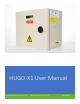

HUGO-X1 User Manual
www.safeguardpowersolutions.com 855.484.6797 P a g e | 9
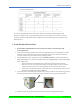
shown in schedule below.
At any time, the HUGO-X1 detects overload or under/over voltage as indicated by the LED
display or chirping alarm, it will attempt delay restarts. Once such issue is resolved, i.e. battery
charge is normal or load is under 350w, the HUGO-X1 will automatically restart and remove any
fault indicators.
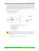
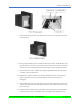
7. FLOW SENSOR INSTALLATION:
NOTE: Before installing the flow sensor, make sure water is shut off at the cold-
water supply side.
Flow sensor should be installed in the cold-water piping with the arrow pointing in the same
direction as the cold-water flow (towards the tankless water heater) and in the horizontal
orientation with the 4 screws of the sensor pointing upward.
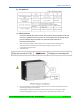
The included flow sensor will require two (2), installer provided, ¾” Female Hose Thread
(FHT, FGH) Adapters to transition from Male Hose Thread (MHT/MGH) to desired piping (PEX,
CPVC, Copper, Etc.)
o Ensure Female Hose Thread Adaptors utilize proper sealing gaskets (washers).
o Make sure to never over-tighten the adaptors to the flow sensor. It is also critical to
align the threads correctly to avoid stripping of the threads on the flow sensor.
o If flow sensor is installed outdoors, please make sure it is properly jacketed to protect
from direct sunlight and freezing conditions.
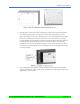
Once Flow Sensor is installed and tested for leaks, connect the flow sensor Molex plug securely
into flow signal interface located in the wiring compartment on the right side of the unit.
After flow sensor is properly installed, turn on the cold-water supply and check for