
User's Manual
User Guide for Chrome 400 Series Graphics
SG192-C.1 10/17/2008
Page 12
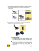
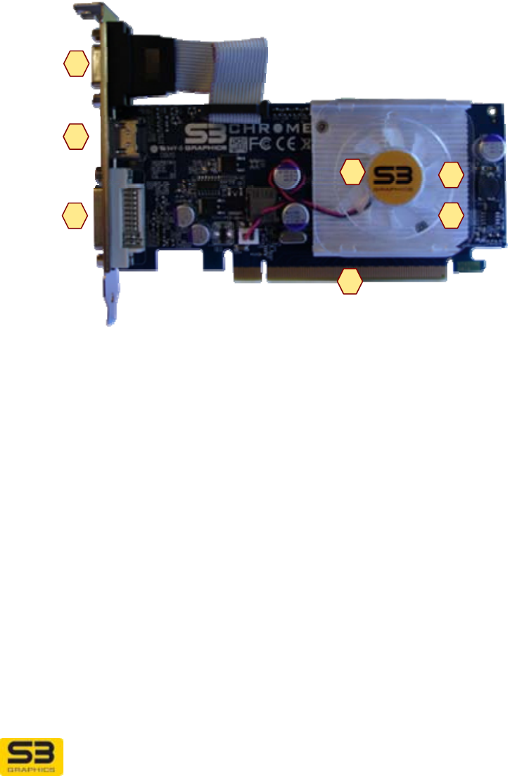
2.2 Your Board Components
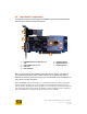
The following diagram shows a typical CHROME 400 Series PCIe board layout
with its major components and connections.
1 CHROME 400 Series GPU (under fan-
sink)
2 Video RAM
(under fan-sink)
3 Fan-sink
4 PCIe Interface
5 CRT Receptacle
6 HDMI Receptacle
7 DVI Receptacle
Note: Your board may appear different than the above example. For instance,
your board may be blue in color instead of green. Or your board may have a
different fan-sink. Or your board may have a second HDMI or DVI receptacles, or
may not have a CRT receptacle.
Note: CHROME 440 GTX boards (rev C and later) include a jumper (J8) which
can be used to disable Gen 2. To disable Gen 2 and force the board to Gen 1,
set the jumper J8 position to Position 2(Pin 2 and center pin). (Most users will not
need to toggle this jumper. When the jumper is either missing or set to Position 1
(Pin 1 and center pin, factory setting), then Gen 2.0 is enabled.
6
5
7
2
1
4
3