
User's Manual

User Guide for Chrome 400/500 Series Graphics
SG195-B.1 1/6/2009
Page 12
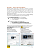
2.2 Your Board Components
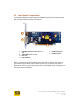
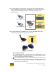
The following diagram shows a typical CHROME 500 Series PCIe board layout
with its major components and connections.
1 CHROME 500 Series GPU (under fan-
sink)
2 Video RAM
(under fan-sink)
3 Fan-sink
4 PCIe Interface
5 HDMI Receptacle
6 DVI Receptacle
Note: Your board may appear different than the above example. For instance,
your board may be blue in color instead of green. Or your board may have a
different fan-sink. Or your board may have a second HDMI or DVI receptacles, or
may have a CRT receptacle.
6
5
2
1
4
3