DGFr 6000-3470-0000-1XX 34700-2019 V110 01 ⁄ 2019 AERASGARD® D RFTM - LQ - CO2 - Modbus Bedienungs- und Montageanleitung Multifunktionaler Raumfühler bzw.
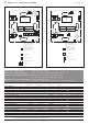
DGFr AERASGARD® RFTM - LQ - CO2 - Modbus Maßzeichnung Dimensional drawing Plan coté Габаритный чертеж R CO2 - Modbus RLQ - CO2 - Modbus RFTM - CO2 - Modbus RFTM - LQ - CO2 - Modbus 98 98 TK :ø 60 32.6 Maßzeichnung Dimensional drawing Plan coté Габаритный чертеж RFTM - CO2 - Modbus - P 34.6 98 98 TK :ø 60 32.
D AERASGARD ® RFTM - LQ - CO 2 - Modbus Rev. 2019 - V23 Der wartungsfreie mikroprozessorgesteuerte AERASGARD ® RFTM - LQ - CO 2 - Modbus bzw. RCO 2 ⁄ RLQ - CO 2 ⁄ RFTM - CO 2 - Modbus mit Modbus- Anschluss, wahlweise mit ⁄ ohne Display, im formschönen Gehäuse aus K unststoff, mit Schnappdeckel, Unterteil mit 4-Lochbefestigung, dient zur Erfassung der Messg rößen Luftfeuchtigkeit, Temperatur, CO 2 -Konzentration sowie Luftq ualität (VOC) in einem Gerät.
D AERASGARD ® RFTM - LQ - CO 2 - Modbus Rev. 2019 - V23 R xx CO 2 - Modbus Schaltbild Stecker Display DIP A: Busadresse DIP B: Busparameter (Baudrate, Parity ...) Telegramm-Anzeige. 1 2grün) 3 4 Empfang (LED Fehler (LED rot) shield Sensor VOC Sensor shield CO2 Stecker Display Sensor CO2 U+ GND A B U+ GND A B 1 2 3 4 RFTM - CO 2 - Modbus - P Schaltbild S Schirmung 1 2 3 4 Stecker Display Sensor VOC Sensor ON Offset-Korrektur LED (interner Status) Reset-Taster1 2 3 4 °C r.H.
D AERASGARD ® RFTM - LQ - CO 2 - Modbus Rev. 2019 - V23 ACHTUNG ! Die minimale CO 2 - Konzentration von Außenluft beträgt in begrünten, industriearmen Gegenden ca. 350 p pm (Ausgangsspannung = 1,75 V bei MB = 0...2000 p pm bzw. 0,7 V bei MB = 0...5000 p pm). Der Gasa ustausch im Sensorelement erfolgt durch Diffusion. Je nach Konzentrationsänderung und Strömungsg eschwindigkeit der Luft in S ensorumgebung kann die Reaktion des Gerätes auf die Konzentrationsänderung verzögert auftreten.
D AERASGARD ® RFTM - LQ - CO 2 - Modbus | Konfiguration Rev. 2019 - V30 intro BUSADRESSE MODBUS DIP-Schalter [A] Busadresse (binärcodiert, Wertigkeit 1 bis 247 einstellbar) DIP 1 DIP 2 DIP 3 DIP 4 DIP 5 DIP 6 DIP 7 DIP 8 128 64 32 16 8 4 2 1 ON ON OFF OFF OFF OFF OFF ON ON DIP A 12 34567 8 Beispiel zeigt 128 + 64 + 1 = 193 als Modbus-Adresse. Die Geräteadresse im Bereich von 1 bis 247 (Binärformat) wird über den DIP-Schalter [A] eingestellt. Schalterstellung Pos.
D AERASGARD ® RFTM - LQ - CO 2 - Modbus | Konfiguration ANZEIGE IM DISPLAY Standardmäßig werden im Display die Messw erte mit den e ntsprechenden Einheiten zyklisch nacheinander angezeigt: CO2 -Gehalt in ppm, Luftq ualität (VOC) in %, T emperatur in °C, relative Feuchte in % r.H. Über die Modbusschnittstelle kann anstelle der Standard-Anzeige eine alternative A usgangsg röße programmiert werden: CO2 -Gehalt in ppm, Luftq ualität (VOC) in %, T emperatur in °C, relative Feuchte in % r.H.
D AERASGARD ® RFTM - LQ - CO 2 - Modbus | Konfiguration ASCII-Code-Tabelle für Dot Matrix Anzeigebereich ASCII Sign ASCII Sign ASCII Sign ASCII Sign ASCII 32 Leer 53 5 73 I 94 ^ 114 r 33 ! 54 6 74 J 95 _ 115 s 34 “ 55 7 75 K 96 \ 116 t 35 # 56 8 76 L 97 a 117 u 36 $ 57 9 77 M 98 b 118 v 37 % 58 : 78 N 99 c 119 w 38 & 59 ; 79 O 100 d 120 x 40 ( 60 < 80 P 101 e 121 y 41 ) 61 = 81 Q 102 f 122 z 42 * 62 > 82
D AERASGARD ® RFTM - LQ - CO 2 - Modbus | Telegramme TELEGRAMME Function 04 Read Input Register Register 3x0001 Parameter CO2 Data Type Value Abtastung 4 s Signed 16 Bit 350...5000 350...5000 ppm Range 350...5000 ppm 3x0002 CO2 Filterung 32 s Signed 16 Bit 350...5000 3x0003 VOC Abtastung 4 s Signed 16 Bit 0...1000 0.0...100.0 % VOC 3x0004 VOC Filterung 32 s Signed 16 Bit 0...1000 0.0...100.0 % VOC 3x0005 Temperatur Abtastung 4 s Signed 16 Bit 0...500 0.0...+50.
D AERASGARD ® RFTM - LQ - CO 2 - Modbus | Telegramme Function 05 Write Single Coil Register 0x0001 Parameter Reset (Autozero) CO2 Data Type Value Range Bit 0 0/1 OFF - ON 0x0002 Reset (Autozero) VOC Bit 1 0/1 OFF - ON 0x0003 automatische Kalibrierung (Automatic) CO2 Bit 2 0/1 OFF - ON OFF - ON 0x0004 automatische Kalibrierung (Automatic) VOC Bit 3 0/1 0x0005 VOC-Sensibilität "low" Bit 4 0/1 OFF - ON 0x0006 VOC-Sensibilität "medium" Bit 5 0/1 OFF - ON 0x0007 VOC-Sensibilitä
D AERASGARD ® RFTM - LQ - CO 2 - Modbus | Installation Rev. 2015 - 1.
D Montage und Inbetriebnahme Hinweise zur Montage: Der Einbau hat unter Berücksichtigung der einschlägigen, für den Messo rt gültigen Vorschriften und Standards (wie z. B. Schweißv or schriften usw.) zu erfolgen.
D Wichtige Hinweise Als AGB gelten ausschließlich unsere sowie die gültigen „Allgemeinen Lieferbedingungen für Erzeugnisse und Leistungen der Elektroi ndustrie“ (ZVEI Bedingungen) zuzüglich der Ergänzungsklausel „Erweiterter Eigentumsvorbehalt“. Außerdem sind folgende Punkte zu beachten: – Der Anschluss der Geräte darf nur an Sicherheitskleinspannung und im spannungslosen Zustand erfolgen. Um Schäden und Fehler am Gerät (z.B.
G AERASGARD ® RFTM - LQ - CO 2 - Modbus Rev. 2019 - V23 The maintenance-free, microprocessor-controlled AERASGARD ® RFTM - LQ - CO 2 - Modbus and RCO 2 ⁄ RLQ - CO 2 ⁄ RFTM - CO 2 - Modbus with Modbus connection, with ⁄ without optional display, in an elegant enclosure, plastic, with snap-on lid, base with 4-hole attachment, is used to to monitor the entire room climate. For this purpose, measurands air humidity, temperature, CO 2 concentration as well as air quality (VOC) are measured.
G AERASGARD ® RFTM - LQ - CO 2 - Modbus R xx CO 2 - Modbus Schematic diagram Plug for display DIP A: Bus address DIP B: Bus parameters (Baud rate, parity ...) Telegram indicator 1 2green) 3 4 Reception (LED Error (LED red) shield Sensor VOC Sensor shield RFTM - CO 2 - Modbus - P Schematic diagram CO2 Plug for display Sensor CO2 U+ GND A B U+ GND A B 1 2 3 4 Rev.
G AERASGARD ® RFTM - LQ - CO 2 - Modbus Rev. 2019 - V23 ATTENTION! The minimum CO 2 concentration of outdoor air amounts to approx. 350 p pm (output voltage = 1.75 V at MR = 0...2000 ppm or 0.7 V at MR = 0...5000 ppm) in leafy, hardly industrialised areas. Gas inter-exchange in the sensor element happens by diffusion.
G AERASGARD ® RFTM - LQ - CO 2 - Modbus | Configuration Rev. 2019 - V30 intro BUS ADDRESS MODBUS DIP switch [A] Bus address (binary coded, value selectable from 1 to 247) DIP 1 DIP 2 DIP 3 DIP 4 DIP 5 DIP 6 DIP 7 DIP 8 128 64 32 16 8 4 2 1 ON ON OFF OFF OFF OFF OFF ON ON DIP A 12 34567 8 Example shows 128 + 64 + 1 = 193 as Modbus address. The device address in the range of 1 to 247 is set at DIP switch [A].
G AERASGARD ® RFTM - LQ - CO 2 - Modbus | Configuration READOUT IN THE DISPLAY By default, the display indicates the following measurements with the corresponding units cyclically and consecutively: CO2 content in ppm, air quality (VOC) in %, temperature in °C, relative humidity in % r.H. The Modbus interface can be used to program an alternative output variable instead of the standard display: CO2 content in ppm, air quality (VOC) in %, temperature in °C, relative humidity in % r.H.
G AERASGARD ® RFTM - LQ - CO 2 - Modbus | Configuration ASCII Code Table for Dot Matrix Display Area ASCII Sign ASCII Sign ASCII Sign ASCII Sign ASCII 32 Blank 53 5 73 I 94 ^ 114 r 33 ! 54 6 74 J 95 _ 115 s 34 “ 55 7 75 K 96 \ 116 t 35 # 56 8 76 L 97 a 117 u 36 $ 57 9 77 M 98 b 118 v 37 % 58 : 78 N 99 c 119 w 38 & 59 ; 79 O 100 d 120 x 40 ( 60 < 80 P 101 e 121 y 41 ) 61 = 81 Q 102 f 122 z 42 * 62 > 82 R
G AERASGARD ® RFTM - LQ - CO 2 - Modbus | Telegrams TELEGRAMS Function 04 Read Input Register Register 3x0001 Parameter CO2 Sampling 4 s Data Type Value Signed 16 bit 350...5000 Range 350...5000 ppm 3x0002 CO2 Filtering 32 s Signed 16 bit 350...5000 350...5000 ppm 3x0003 VOC Sampling 4 s Signed 16 bit 0...1000 0.0...100.0 % VOC 3x0004 VOC Filtering 32 s Signed 16 bit 0...1000 0.0...100.0 % VOC 3x0005 Temperature Sampling 4 s Signed 16 bit 0…500 0.0...+50.
G AERASGARD ® RFTM - LQ - CO 2 - Modbus | Telegrams Function 05 Write Single Coil Register 0x0001 Parameter Reset (Auto zero) CO2 Data Type Value Range Bit 0 0/1 OFF - ON 0x0002 Reset (Auto zero) VOC Bit 1 0/1 OFF - ON 0x0003 Automatic calibration (Automatic) CO2 Bit 2 0/1 OFF - ON OFF - ON 0x0004 Automatic calibration (Automatic) VOC Bit 3 0/1 0x0005 VOC sensibility "low" Bit 4 0/1 OFF - ON 0x0006 VOC sensibility "medium" Bit 5 0/1 OFF - ON 0x0007 VOC sensibility "high"
G AERASGARD ® RFTM - LQ - CO 2 - Modbus | Installation Rev.
G Installation and Commissioning Notes on installation: Mounting shall take place while observing all relevant regulations and standards applicable for the place of measurement (e.g. such as welding instructions, etc.). Particularly the following shall be regarded: – VDE ⁄ VDI directive technical temperature measurements, measurement set - up for temperature measurements. – The EMC directives must be adhered to. – It is imperative to avoid parallel laying of current-carrying lines.
G Important notes Our “General Terms and Conditions for Business“ together with the “General Conditions for the Supply of Products and Services of the Electrical and Electronics Industry“ (ZVEI conditions) including supplementary clause “Extended Retention of Title“ apply as the exclusive terms and conditions. In addition, the following points are to be observed: – Devices must only be connected to safety extra-low voltage and under dead-voltage condition. To avoid damages and errors at the device (e.g.
F AERASGARD ® RFTM - LQ - CO 2 - Modbus Rev. 2019 - V23 La sonde AERASGARD ® RFTM - LQ - CO 2 - Modbus ou RCO 2 ⁄ RLQ - CO 2 ⁄ RFTM - CO 2 - Modbus commandée par microprocesseur sans entretien, avec raccordement Modbus, au choix avec / sans écran, dans un boîtier élégant en plastique, avec couvercle emboîté, partie inférieure avec fixation à 4 trous, sert à enregistrer les données relatives au climat ambiant dans son ensemble.
F AERASGARD ® RFTM - LQ - CO 2 - Modbus R xx CO 2 - Modbus Schéma de raccordement Plug for display DIP A: Bus address DIP B: Bus parameters (Baud rate, parity ...) Telegram indicator 1 2green) 3 4 Reception (LED Error (LED red) shield Sensor VOC Sensor shield RFTM - CO 2 - Modbus - P Schéma de raccordement CO2 Plug for display Sensor CO2 U+ GND A B U+ GND A B 1 2 3 4 Rev.
F AERASGARD ® RFTM - LQ - CO 2 - Modbus Rev. 2019 - V23 ATTENTION ! La teneur minimale en CO 2 de l'air extérieur dans des régions vertes à faible degré d'industrialisation est de l'ordre 350 p pm (tension de sortie = 1,75 V à MB = 0...2000 p pm, resp. 0,7 V à MB = 0...5000 ppm). L'échange de gazdans l'élément capteur s'effectue par diffusion.
F AERASGARD ® RFTM - LQ - CO 2 - Modbus | Configuration Rev. 2019 - V30 intro ADRESSE DU BUS MODBUS Interrupteur DIP [A] Adresse du bus (code binaire, valance réglable de 1 à 247) DIP 1 DIP 2 DIP 3 DIP 4 DIP 5 DIP 6 DIP 7 DIP 8 128 64 32 16 8 4 2 1 ON ON OFF OFF OFF OFF OFF ON ON DIP A 12 34567 8 suit l'adresse Modbus 128 + 64 + 1 = 193 L'adresse de l'appareil dans une plage de 1 à 247 (format binaire) est réglée via l'interrupteur DIP [A].
F AERASGARD ® RFTM - LQ - CO 2 - Modbuss | Configuration AFFICHAGE SUR L'ÉCRAN Par défaut, les valeurs de mesure suivantes sont affichées de manière cyclique, les unes après les autres dans l'écran avec les unités correspondantes : Teneur en CO2, qualité de l'air (COV) en %, température en °C, humidité relative en % h.r.
F AERASGARD ® RFTM - LQ - CO 2 - Modbus | Configuration Tableau des codes ASCII pour la zone d'affichage de la matrice de points ASCII Sign ASCII Sign ASCII Sign ASCII Sign ASCII 32 Espace 53 5 73 I 94 ^ 114 r 33 ! 54 6 74 J 95 _ 115 s 34 “ 55 7 75 K 96 \ 116 t 35 # 56 8 76 L 97 a 117 u 36 $ 57 9 77 M 98 b 118 v 37 % 58 : 78 N 99 c 119 w 38 & 59 ; 79 O 100 d 120 x 40 ( 60 < 80 P 101 e 121 y 41 ) 61 = 81 Q 102 f
F AERASGARD ® RFTM - LQ - CO 2 - Modbus | Télégrammes TÉLÉGRAMMES Function 04 Read Input Register Registre Paramètre Data Type Value Signed 16 Bit 350…5000 350...5000 ppm Filtrage 32 s Signed 16 Bit 350…5000 350...5000 ppm Balayage 4 s Signed 16 Bit 0…1000 0.0...100.0 % COV COV Filtrage 32 s Signed 16 Bit 0…1000 0.0...100.0 % COV 3x0005 Température Balayage 4 s Signed 16 Bit 0…500 0.0...+50.0 °C 3x0006 Température Filtrage 32 s Signed 16 Bit 0…500 0.0...+50.
F AERASGARD ® RFTM - LQ - CO 2 - Modbus | Télégrammes Function 05 Write Single Coil Registre 0x0001 Paramètre Réinitialisation (Autozero) CO2 Data Type Value Range Bit 0 0/1 OFF - ON 0x0002 Réinitialisation (Autozero) COV Bit 1 0/1 OFF - ON 0x0003 Calibrage automatique (Automatic) CO2 Bit 2 0/1 OFF - ON OFF - ON 0x0004 Calibrage automatique (Automatic) COV Bit 3 0/1 0x0005 Sensibilité COV "low" Bit 4 0/1 OFF - ON 0x0006 Sensibilité COV "medium" Bit 5 0/1 OFF - ON 0x0007 Se
F AERASGARD ® RFTM - LQ - CO 2 - Modbus | Installation Rev.
F Montage et mise en service Consignes demontage : L'installation doit être effectuée en conformité avec les réglementations et les normes en vigueur pour le lieu de mesure (par ex. règles de soudage, etc.).
F Généralités Seules les CGV de la société S+S, les « Conditions générales de livraison du ZVEI pour produits et prestations de l'industrie électronique » ainsi que la clause complémentaire « Réserve de propriété étendue » s'appliquent à toutes les relations commerciales entre la société S+S et ses clients. Il convient en outre de respecter les points suivants : – Les appareils ne doivent être raccordés qu'à une très basse tension de sécurité et à l'état hors tension.
r AERASGARD ® RFTM - LQ - CO 2 - Modbus Rev. 2019 - V23 Не нуждающийся в техническом обслуживании, управляемый микропроцессором датчик AERASGARD ® RFTM - LQ - CO 2 - Modbus или RCO 2 ⁄ RLQ - CO 2 ⁄ RFTM - CO 2 - Modbus с возможностью подключения к шине Modbus, на выбор с дисплеем или без дисплея, в элегантном корпусе из пластика, с защелкивающейся крышкой, низ с четырьмя отверстиями, служит для о пределения микроклимата в помещении.
r AERASGARD ® RFTM - LQ - CO 2 - Modbus R xx CO 2 - Modbus Схема подключения CO2 Plug for display Sensor CO2 U+ GND A B U+ GND A B DIP A: Bus address DIP B: Bus parameters (Baud rate, parity ...) Telegram indicator 1 2green) 3 4 Reception (LED Error (LED red) shield Sensor shield RFTM - CO 2 - Modbus - P Схема подключения Sensor VOC Plug for display 1 2 3 4 Rev.
r AERASGARD ® RFTM - LQ - CO 2 - Modbus Rev. 2019 - V23 ВНИМАНИЕ! Минимальная концентрация CO 2 в наружном воздухе в озелененных районах с малым количеством промышленных объектов составляет прибл. 350 млн -1 (выходное напряжение = 1,75 В при диапазоне измерения 0...2000 млн -1 или 0,7 В при диапазоне измерения 0...5000 млн -1). Газообмен в чувствительном элементе осуществляется благодаря диффузии.
r AERASGARD ® RFTM - LQ - CO 2 - Modbus | Конфигурация Rev. 2019 - V30 intro А ДРЕС ШИНЫ MODBUS DIP-переключатель [A] Адрес шины (двоичный, настраиваемая значимость от 1 до 247) DIP 1 DIP 2 DIP 3 DIP 4 DIP 5 DIP 6 DIP 7 DIP 8 128 64 32 16 8 4 2 1 ON ON OFF OFF OFF OFF OFF ON Данный пример показывает, что 128 + 64 + 1 = 193 — это адрес шины Modbus. ON DIP A 12 34567 8 Адрес прибора в диапазоне от 1 до 247 (двоичный формат) настраивается с помощью DIP-переключателя [A].
r AERASGARD ® RFTM - LQ - CO 2 - Modbus | Конфигурация ИНДИК АЦИЯ НА ДИСПЛЕЕ В стандартном исполнении на дисплее поочередно и циклично отображаются следующие измеренные значения с соответствующими единицами измерения: содержание углекислого газа (млн -1), качество воздуха (VOC; %), температура (°C), относительная влажность (% отн. влажн.
r AERASGARD ® RFTM - LQ - CO 2 - Modbus | Конфигурация Таблица кодов ASCII для полей с точечной матрицей ASCII Символ ASCII Символ ASCII Символ ASCII Символ ASCII 32 Пробел 53 5 73 I 94 ^ 114 r 33 ! 54 6 74 J 95 _ 115 s 34 “ 55 7 75 K 96 \ 116 t 35 # 56 8 76 L 97 a 117 u 36 $ 57 9 77 M 98 b 118 v 37 % 58 : 78 N 99 c 119 w 38 & 59 ; 79 O 100 d 120 x 40 ( 60 < 80 P 101 e 121 y 41 ) 61 = 81 Q 102 f 122 z 42 *
r AERASGARD ® RFTM - LQ - CO 2 - Modbus | Телеграммы ТЕЛЕГРАММЫ Функция 04 — Чтение регистров ввода (Read Input Register) Регистр Тип данных Значение Диапазон 3x0001 CO2 Параметр Считывание 4 с Со знаком 16 бит 350...5000 350...5000 млн -1 3x0002 CO2 Фильтрация 32 с Со знаком 16 бит 350...5000 350...5000 млн -1 3x0003 VOC Считывание 4 с Со знаком 16 бит 0...1000 0,0...100,0 % 3x0004 VOC Фильтрация 32 с Со знаком 16 бит 0...1000 0,0...
r AERASGARD ® RFTM - LQ - CO 2 - Modbus | Телеграммы Функция 05 — Запись значения одного флага (Write Single Coil) Регистр Тип данных Значение 0x0001 Сброс (Autozero) CO2 Параметр Бит 0 0/1 Диапазон OFF - ON 0x0002 Сброс (Autozero) VOC Бит 1 0/1 OFF - ON 0x0003 Автоматическая калибровка (Automatic) CO2 Бит 2 0/1 OFF - ON 0x0004 Автоматическая калибровка (Automatic) VOC Бит 3 0/1 OFF - ON 0x0005 Чувствительность VOC «low» Бит 4 0/1 OFF - ON 0x0006 Чувствительность VOC «medium»
r AERASGARD ® RFTM - LQ - CO 2 - Modbus | Подключение Rev.
r Монтаж и ввод в эксплуатацию Указания по монтажу: Монтаж должен осуществляться с учетом соответствующих, действительных для места измерения предписаний и стандартов (например, инструкции для сварочных работ).
r Важные указания В качестве общих коммерческих условий действуют исключительно наши условия, а также действительные «Общие условия поставки продукции и услуг для электрической промышленности» (ZVEI), включая дополнительное условие «Оговорка о сохранении права собственности». Помимо этого, следует учитывать следующие положения: – Подк лючать прибор иск лючительно к безопасно малому напряжению и в обесточенном состоянии.
DGFr AERASGARD® RFTM - LQ - CO2 - Modbus Gehäuse Enclosure Boîtier Корпус Zum Öffnen des Gehäuses einen Schraubendreher (2,0) in die Nut mittig ansetzen, nach unten drücken und den B odenrahmen etwas anheben. Den Deckel nach vorne ziehen und halten. Baldur To open the enclosure, set a screwdriver (2.0) in the groove at c entre, press down, and lift up the bottom frame slightly. Pull top cover forward and hold it.
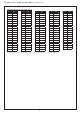
DGFr Busadresse, binärcodiert Bus address, binary coded Adresse du bus, code binaire Адресс шины, двоичный 1 2 3 4 5 6 7 8 9 10 11 12 13 14 15 16 17 18 19 20 21 22 23 24 25 26 27 28 29 30 31 32 33 34 35 36 37 38 39 40 41 42 43 44 45 46 47 48 49 50 00000001 00000010 00000011 00000100 00000101 00000110 00000111 00001000 00001001 00001010 00001011 00001100 00001101 00001110 00001111 00010000 00010001 00010010 00010011 00010100 00010101 00010110 00010111 00011000 00011001 00011010 00011011 00011100 00011101 0