
Brochure


13
G
PREMASGARD
®
1110
Rev. 2017 - V12 GB
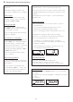
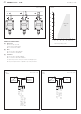
Schematic diagram*
PREMASGARD
®
1110
Output: with ⁄ without display
4...20 mA
DIP switch 6
is not assigned!
Schematic diagram
PREMASGARD
®
1110
Output: with ⁄ without display
0 -10 V
DIP switch 6
is not assigned!
Connection
*
:
2-wire connection for devices with ⁄ without display (not illuminated)
3-wire connection for devices with illuminated display
1 2 3
123456
ON
Pushbutton
Offset
Plug for display
contact is
on the right side
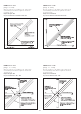
Zero point setting
(auto zero)
Offset correction
see graph
ca.± 10% of
final value
Plug for
display
Offset
auto
zero
LED
DIP
switches
min. max.
Output pressure 0-10V in Pa
–UB GND
+UB 24V AC/DC
1 2 3
123456
ON
Pushbutton
Offset
Plug for display
contact is
on the right side
Zero point setting
(auto zero)
Offset correction
see graph
ca.± 10% of
final value
Plug for
display
Offset
auto
zero
LED
DIP
switches
min. max.
+UB 24V DC
Output pressure Pa 4...20mA
GND
(optional for LCD
backlighting)
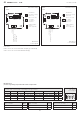
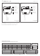
DIP switches for
pressure range setting, output attenuation and zero compensation:
Pressure range
(selectable, max. measuring range is depending to the type of device)
PREMASGARD
®
1110
DIP switch 6
is not assigned!
0...1000 Pa 0...5000 Pa 0...10000 Pa –1000...+1000 Pa –5000...+5000 Pa –10000...+10000 Pa
DIP 1 DIP 2
0...100 Pa 0...1000 Pa 0...4000 Pa –100...+100 Pa –1000...+1000 Pa –4000...+4000 Pa
OFF
OFF
0...300 Pa 0...2000 Pa 0...6000 Pa –300...+300 Pa –2000...+2000 Pa –6000...+6000 Pa O N
OFF
0...500 Pa 0...3000 Pa 0...8000 Pa –500...+500 Pa –3000...+3000 Pa –8000...+8000 Pa
OFF
O N
0...1000 Pa 0...5000 Pa 0...10000 Pa –1000...+1000 Pa –5000...+5000 Pa –10000...+10000 Pa O N O N
Measuring range mode
(Mode selectable)
DIP 3
Output characteristic line
(Mode selectable)
DIP 4
Measurement signal filtering
(Time interval selectable)
DIP 5
Unidirectional ( 0 ...+MR ) OFF Linear OFF Long (10 s) OFF
Bidirectional (–MR ...+MR )
O N
Square root extracting
O N
Small (1 s)
O N