
Brochure


12
G
PREMASGARD
®
1110
Rev. 2017 - V12 GB
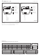
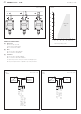
Connecting diagram
PREMASGARD
®
1110
Output: with ⁄ without display
4...20 mA
Connecting diagram
PREMASGARD
®
1110
Output: with ⁄ without display
0 -10 V
-
+
+
-
1 2 3
230
V AC
PLC
Working
resistance
24
V DC
+UB 24V DC
Output pressure Pa 4-20mA
GND
(optional for LCD
backlighting)
-
+
+
-
1 2 3
230
V AC
24V AC/DC
PLC
PC
+UB 24V AC/DC
Output 0 -10 V
-UB AC/DC GND
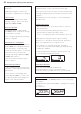
Mounting diagram
PREMASGARD
®
1110
Compact form
110 Pa 110 Pa 110 Pa
(A) (B) (C)
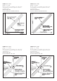
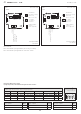
Load resistance diagram
PREMASGARD
®
1110
4...20 mA
800
700
600
500
400
300
250
50
200
10 15 20 25 30 35 36 40
Load resistance diagram
Working resistance (Ohm)
Operating voltage (V DC)
Admissible
range
800
700
600
500
400
300
250
50
200
10 15 20 25 30 35 36 40
Load resistance diagram
Working resistance (Ohm)
Operating voltage (V DC)
Admissible
range
TYPES OF MONITORING:
(A) Below-atmospheric pressure:
P1(
+
) is not connected but open against atmosphere
P2(
–
) connected to inside of duct
(B) Filter:
P1(
+
) connected upstream of filter
P2(
–
) connected downstream of filter
(C) Ventilator:
P1(
+
) connected downstream of ventilator
P2(
–
) connected upstream of ventilator
Pressure connections at the pressure switch are marked with
P1(
+
) for higher pressure and
P2(
–
) for lower pressure.