
User Manual

Piston Kit Contents
• (2) 3.937" pistons (front and rear
pistons are the same)
• (2) 0.927" piston pins
• (4) Piston pin clips with
installation tool
• (2) Ring packs which include
the top, second, oil rail, and
expander rings
Piston and Cylinder Kit
Contents
• (1) 3.937" Piston Kit
• (2) 3.937" Bore Cylinders
• (2) MLS (Multi Layer Steel) head
gaskets, 0.045" thick
• (2) Cylinder base O-rings
• (2) Cylinder base dowel O-rings
• (2) Exhaust gaskets
Special Tool Requirements
• Harley-Davidson service manual
for the specic model you are
working on
• Piston ring compressor
• Piston ring expander
• Piston ring end gap ling tool
• Digital or dial calipers
• Feeler gauges
• Torque Wrench
Instruction Contents
• General Information
• Disassembly
• Installation and Reassembly
1. Boring Cylinders
2. Setting Ring End Gap
3. Piston Ring Installation
4. Piston Installation
5. Cylinder Installation
6. Cylinder Head Installation
7. Final Assembly
8. Tuning
9. Break-in Procedure
General Information
• Thoroughly read and understand all the instructions before starting
installation.
• S&S 107" big bore kits contain 3.937" bore pistons with 1.085" deck
height. These kits are intended for stock stroke (4.375") 2007–‘14 big
twin engines.
• S&S 98" big bore kits contain 3.937" bore pistons with 1.265" deck
height. These kits are intended for stock stroke (4.000") 1999–’06 big
twin engines.
• Pistons in both kits are the same for the front and rear cylinders and
can be used with either cylinder.
• CAUTION: THE PISTONS MUST BE ORIENTED SO THAT THE VALVE
RELIEFS MATCH THE CORRESPONDING VALVES. THE INTAKE
VALVE RELIEF IS LARGER THAN THE EXHAUST VALVE RELIEF.
THE 107" PISTONS HAVE A NOTCH ON THE BOTTOM OF THE
SKIRT, THIS NOTCH MUST BE INSTALLED TOWARD THE CENTER
OF THE ENGINE. THE 98" PISTONS DO NOT HAVE A NOTCH AND
MUST BE INSTALLED WITH THE VALVE RELIEFS ORIENTED TO THE
APPROPRIATE VALVE.
• The pistons are machined during manufacturing, to provide the
correct running clearance when cylinders are bored to nominal size of
3.937". In other words the clearance is built into the piston diameter.
If you wish to conrm piston diameter, measure the diameter 0.5"
up from the bottom of the piston skirts (see Specication Sheet for
details). Cylinder measurements must be taken with the cylinder in
torque plates with bolts tightened at correct torque value to simulate
conditions in an assembled engine.
• In all cases it is the engine builder’s responsibility to conrm proper
clearances when assembling an engine. This is especially critical with
performance components such as larger valve, high performance
heads and high lift camshafts.
• In addition to clearances mentioned, 0.060" valve to piston clearance
must be conrmed.
CAUTION
Failure to follow instructions and perform required clearancing,
installation and/or break-in procedures may result in damage
to pistons and or other engine components not covered under
warranty. The proper break-in procedure is in Section 9 of these
instructions.
DISASSEMBLY
Refer to the Harley-Davidson® manual for your specic motorcycle for
the correct disassembly procedure.
The engine should be disassembled to the short block i.e. induction
system, exhaust system, cylinder heads, cylinders, and pistons should
be removed.
INSTALLATION AND REASSEMBLY
1. Boring Cylinders
If stock Harley-Davidson® cylinders will be bored to accept these pistons,
the following procedures must be used:
a. Torque plates must be used during the boring and honing
operations.
b. Do not use a hand hone.
c. Honing: Use a 220 grit stone until there is 0.001" of material left
from the nal bore. The bore must be round to 0.0002", checked
360˚ around the bore from the bottom to the top of the cylinder.
Use a 280 grit stone at 50% load until there is 0.0002" remaining.
With the 280 grit stone, reduce the load to 20% to achieve the nal
bore size. Final bore size should be 3.937" ± 0.00025".
d. Use a dial bore gauge to accurately measure the cylinder bore.
e. When nished honing, wash the cylinders thoroughly to remove
material trapped in the honing grooves. Failure to clean the cylinder
could lead to premature ring wear and blow-by.
2. Setting Ring End Gaps
NOTES
• Important! The gap of the second ring should be larger than the top ring;
this will help keep the top ring seated for improved performance.
• Each ring should be tted to the particular cylinder in which they will be
installed.
• Oil rails can be installed without adjusting the end gap. The minimum
gap should be 0.015"
• Never alter the end gap of the oil expander ring.
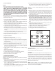
• Always install the ends of the expander facing up as shown in Picture 3,
next page.
a. Thoroughly wash cylinders with hot soapy water, then wash with
brake cleaner and wipe with a clean white towel. Repeat until
towel does not show evidence of debris and apply a light coat of
oil immediately.
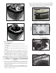
b. Check the ring end gap by placing the ring into the cylinder. Use
a piston or caliper to ensure that the ring is placed squarely in the
bore. See Picture 1.
c. Measure the ring end gap with a feeler gauge. See Picture 2.
d. See Table 1 for proper end gap measurement. If adjustment to the
gap must be made, use a proper ring end gap ling tool.
e. Always le from the ring face towards the inside diameter to avoid
damaging the face coating.
f. Remove material from only one end of the ring.
g. Ensure that ring end gaps are square.
h. Remove sharp edges and burrs.
i. Recheck gap measurement and adjust as necessary.
j. Repeat procedure with the other rings.
2
Ring End Gap
Application Top Ring Second Ring Oil Ring
Street/Hi
Performance
Bore x 0.0045"
0.004"-0.008"
Bigger than top ring
Minimum 0.015"
Do not le
Drag Racing Bore x 0.005"
0.004"-0.008"
Bigger than top ring
Minimum 0.015"
Do not le
Nitrous/Turbo
Supercharged
Bore x 0.0055”
0.004"-0.008"
Bigger than top ring
Minimum 0.015"
Do not le
Table 1