
User guide
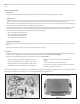
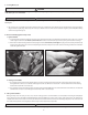
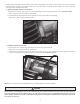
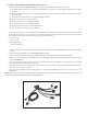

6. Installation of the IST Ignition Module and Main IST Wiring Harness:
(See Picture 13, below)
(a
(b
(c
(d
(e
(f
(g
(h
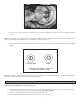
(a) See Picture 13
(a) See Picture 13
(b)
See Picture 13.
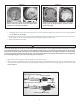
(c), (d), (e) See
Picture 13.
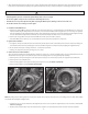
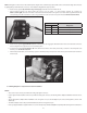
NOTE: If the tank is removed or raised, temporarily replace it to insure clearance for the Engine Temperature, MAP, and Knock Sensor portions of the
harness. Reroute any wires that may be damaged from installing the tank.
9
Picture 13
a
c
e
g
h
b
f
d