
User guide

See Picture 11, above right.
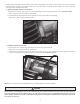
The alignment pins may have some resistance to removal, but both pins should pull out smoothly and evenly. If the pins are dicult to
remove, the stand o screws must be loosened, the plate re-positioned, and the screws re-tightened until the components are correctly
aligned. The alignment pins serve dual purpose: They establish the timing baseline, and center the sensor plate in the cup. The clearance
between the cup “teeth” and the sensor plate is very small and it is of the utmost importance to align this assembly correctly. The dowel
pins must be used every time the cam position sensor is removed and installed, and also any time the hold down screws are tightened.
Torque from tightening the screw heads can twist the plate out of position.
See
Picture 12, below.
8
Picture 10
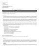
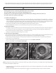
Alignment pin hole locations for initial timing. Pin holes
must be located as pictured, at Top Dead Center of the
compression stroke of the front cylinder
Big Twin
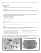
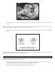
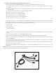
Picture 11
Alignment pin locations for initial timing. Big twin is
shown on the left, Harley-Davidson® Sportster® model is
shown on the right.
CAUTION
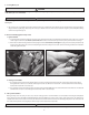
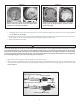
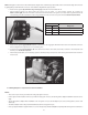
Picture 12
Cam Position Sensor Long Pigtail
Position 1 marked
Positions A, B, and C marked
Locking Wedge
1
A
2
B
3
C
Cam Position Sensor Short Pigtail
Sportster® models