
User guide

•
•
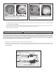
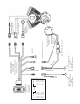
• See Picture 18, above.
F. Initial Starting and Operation Procedure:
1. Initial Starting Procedure
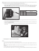
Damage to coil may result if Steps (a) thru (c) below are not followed.
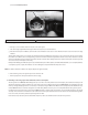
See Picture 13, page 9, item “f”.
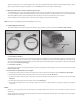
2. Initial Operating Procedure
See Step 2-a.
12
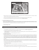
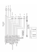
Picture 18
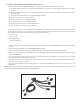
Discard sealing
pins from rear
of connector
green/white
red/white
black/white
2
3
5
CAUTION
Pink tach wire
in #4 is optional
Insert three wires from cam harness into rear of power harness.
Insert wires fully, then replace locking wedge into front of connector.