
User Manual


15
C. Install both cylinders and secure each with one nut.
NOTE:
D. Rotate ywheel until rods contact areas to be clearanced. Note angle that must be led.
E. Disassemble cylinder and connecting rods and le crankcase and cylinder spigot for clearance.
NOTE: A MINIMUM OF ⁄" CLEARANCE IS REQUIRED.
F. Reassemble and check clearance.
G. This procedure must be done for both crankcase halves.
Insucient clearance between connecting rods and crankcases will cause contact and damage to components.
Piston Clearance
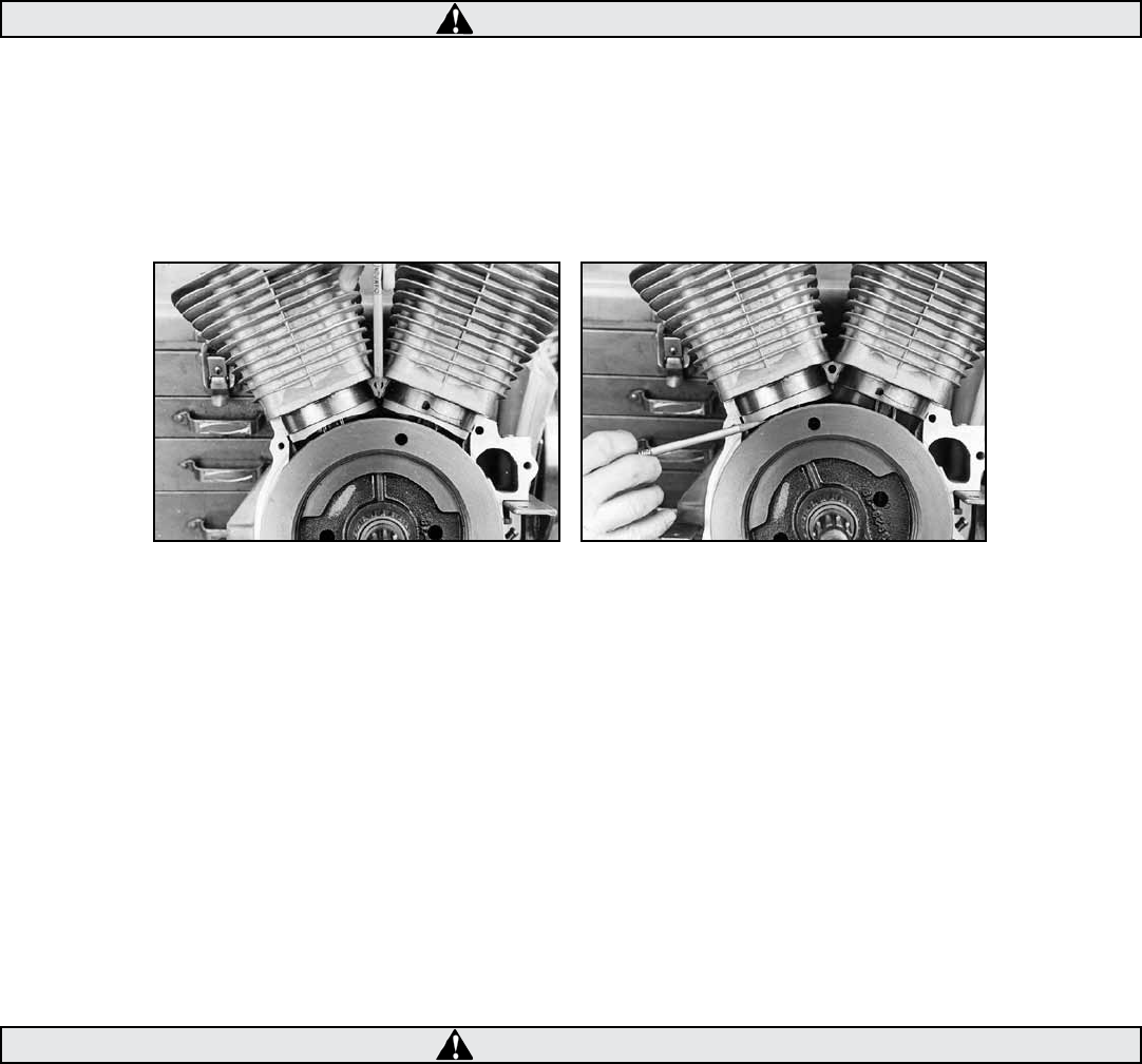
Pistons must be clearanced to avoid contact with each other and with ywheels. See Pictures 8, below right, and 9, below left.
Piston to Piston Clearance
A. Perform steps A through C in “Connecting Rod Clearance” above.
B. Rotate ywheel to position where pistons are closest to each other. See Picture 8.
C. Check clearance between pistons.
NOTE - A MINIMUM OF ⁄" CLEARANCE IS REQUIRED.
D. Disassemble cylinders and pistons, and carefully le edge of piston skirts until clearance is obtained.
E. Reassemble and check clearance.
Piston to Flywheel Clearance
A. Perform steps A through C in “Connecting Rod Clearance” above.
B. Rotate ywheel to position where front piston is closest to ywheel. See Picture 9,above right.
C. Check clearance between piston and ywheel.
NOTE - A MINIMUM OF ⁄" CLEARANCE IS REQUIRED.
D. Disassemble cylinder and piston, and carefully le piston skirt until clearance is obtained.
E. Reassemble and check clearance.
F. Repeat procedure for rear piston.
Insucient clearance between pistons and pistons and ywheels will cause contact and damage to components.
CAUTION
CAUTION
Picture 8 Picture 9