
Manual

3
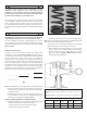
See Figure 2, Dimension B.
Note: If shims are used, they are to be placed under the integral
seal.
Note: Installed spring height is the distance between spring contact
surfaces of top and bottom collar when the valve is closed.
Note: Installed height should be the same for each spring assembly, ±
.010".
CAUTION
• Installing springs at height less than recommended dimension
will cause rapid spring fatigue resulting in possible engine
damage.
• Installing springs at height above recommended dimension will
decrease spring tension resulting in possible valve oat and
engine damage.
• Failure to establish required clearances may cause valve seal
failure and other, more extensive engine damage not covered
under warranty.
WA RNING
Valve spring assembly is under considerable tension when
compressed and is potentially dangerous. Wear eye protection
and take due caution when checking for coil bind and during
installation. After assembly, carefully strike tip of valve stem
with plastic hammer to insure that keepers are seated. Direct
spring assembly away from face and body during this procedure.
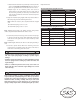
Part Number Item Quantity
90 -2094 -S 8
106 -0739 4
90 -2070 4
90 -2281
4
90 -2086 4
90 -2087 4
.585 Sidewinder Valve Spring Kit 106-0772
Part Number Item Quantity
90 -2094 -S 8
4
4
106 -3827 4
90 -2281
4
4
4
.650 Sidewinder Valve Spring Kit 900-0212