GB USE AND MAINTENANCE MANUAL BC 90 (1+1) ®
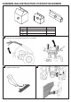
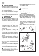
ASSEMBLING INSTRUCTION FOR MOTOR-MOWER S1 S3 S2 BOX CONTENTS WEIGHT (kg) S1 MACHINE 46,5 ÷ 47 S2 BAR MECHANISM 9,8 ÷ 12,5 S3 SICKLE BAR 14 ÷ 21,5 A POSITION THE HANDLEBAR TIGHTEN THE 4 SCREEW B CONNECT SICKLE BAR C
MOTOR-MOWER BC 90 (1+1) BEFORE USING THE MOTOR-MOWER CAREFULLY READ THE INSTRUCTIONS GIVEN IN THIS MANUAL
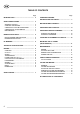
TABLE OF CONTENTS Page INTRODUCTION.................................................... 3 Page TRANSFER PRINTING INSTRUCTIONS AND SAFETY.............................. 7 SAFETY REGULATIONS ....................................... 3 GENERAL NOTICES............................................. STARTING THE ENGINE ...................................... OPERATING OF THE MOTOR-MOWER............... OPERATING OF ATTACHMENTS ........................ MAINTENANCE.....................................................
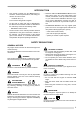
INTRODUCTION • This manual provides Use and Maintenance instructions, technical specifications, and safety precautions for motor-mower: − model BC 90 (1+1) in the versions with gasoline engines. • For the sake of clarity and ease of identification, the different motor-mower models are identified in this manual by means of the following codes: − 90 identifies motor-mower. • The first section of this manual provides technical specifications and gives instructions relevant to the machine.
STARTING THE ENGINE • Disengage all control levers before starting the motor. Keep your feet clear of the attachments fitted to the machine. • Do not run the engine in a closed ambient where the exhaust gases can collect. They contain carbon monoxide that is highly toxic. • Do not interfere with safety device (engine shutoff). Do not use the motor-mower if this safety device is missing or defective. • Oil bath air filter (if fitted) - When delivered new, there is no oil in the air filter.
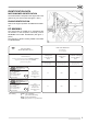
IDENTIFICATION DATA MOTOR-MOWER IDENTIFICATION The serial number is stamped on the engine side of the gear box of your motor-mower (see figure 1, item 1). ENGINE IDENTIFICATION Refer to the engine Operation and Maintenance Manual. EC MARKING The motor-mower is marked EC in compliance with the Directive of the European Community Council 89/392/EEC and further amendments (see figure 1, part 2). The summary of the EC marking related to 90 model is indicated below.
IDENTIFICATION DATA MOTOR-MOWER IDENTIFICATION The serial number is stamped on the engine side of the gear box of your motor-mower (see figure 1, item 1). ENGINE IDENTIFICATION Refer to the engine Operation and Maintenance Manual. EC MARKING The motor-mower is marked EC in compliance with the Directive of the European Community Council 89/392/EEC and further amendments (see figure 1, part 2). The summary of the EC marking related to 90 model is indicated below.
TECHNICAL SPECIFICATIONS COUPLING OF ATTACHMENTS The motor-mower may be fitted with the following engines: Coupling of attachments to the PTO is obtained through a quick change fitting that provides for fast installation of the attachments, and does not require the use of bolts. − HONDA GC 160; 4 stroke benzina; 3,7 kW (5 HP); 160 cm3. HANDLEBARS ENGINE − LOMBARDINI LGA 226; 4 stroke benzina; 4 kW (5,4 HP); 220 cm3. Adjustable in height with dampers.
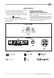
SAFETY DEVICE The machine is fitted with an engine shut-off device to ensure maximum safety in machine operation: − Engine shut-off is an electrical device which stops the engine instantly if the handlebars are released. WARNING Do not interfere with safety device (engine shut-off). Do not use the motor-mower if the safety device is missing or defective. TRANSFER PRINTING INSTRUCTIONS AND SAFETY Please find below the adhesive transfer printing shown on the machine.
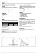
MOTOR-MOWER CONTROLS See fig. 3. 1. Clutch lever. 2. Engine stop lever. OPERATING THE CONTROLS Clutch lever (See figure 4) − Lever (1) pulled up: clutch disengaged. − Lever (1) released: clutch engaged. Engine stop lever (See figure 4) − Lever (2) pressed down: engine running. − Lever (2) released: engine stopped.
Throttle control lever (See figure 7) − Lever (1) in up position: engine at idle. − Lever (1) in down position: max engine rpm. Power Take Off (PTO) control lever The Power Take Off (PTO) control lever engages the drive to the attachment. To engage and disengage drive, proceed as follows (see fig. 6): a. Turn throttle control lever to idle position. b. Pull up clutch lever. c. Pull PTO control lever (1) and release it when drive is engaged (see plate in detail A.) d.
OPERATING THE MOTOR-MOWER STARTING THE ENGINE NOTE See the engine Operating and Maintenance manual for all information regarding the engine. CAUTION Oil bath air filter (if fitted) - When delivered new, there is no oil in the air filter. Before using your motor-mower, add motor oil up to the marked level. d. Gasoline engines: if you plan not to use your motor-mower for a long time (over a week), drain the carburettor bowl.
MOUNTING THE 2ND WHEEL (UPON REQUEST) To mount the 2nd wheel kit, follow the below steps: a. Insert there spacer (3) into the wheel hexagon (1) and fix it by the safety pin (4). b. Install the second wheel (2) and fix it by its screw (6) and washer (5). − This procedure has to be done on both wheels. c. Remove the oil drain plug (2) from the bottom of the gearbox (right side) and let the exhausted oil drain out. When fully drained, reinstall the plug (2). d. Fill up with new oil (1.
Every 300 hours Change the gearbox and transmission oil following the instructions given above in the paragraph covering running in. POWER TAKE OFF Every 8 hours Grease the PTO (see figure 14, item 1). Also grease the PTO every time you fit a new attachment. 12 CHECKS AND ADJUSTMENTS CLUTCH LEVER The clutch lever must have a free play of about 5 to 6 mm before the clutch starts to disengage. Insufficient play can cause clutch slip, while excess play can lead to failure to disengage fully.
CUTTER BAR MOWER WARNING • When you transport your machine, and when you finish work, always fit the knife guard over the cutter bar. • Keep your hands and feet clear of the cutter bar when in motion. • Do not operate the motor-mower in proximity of children and/or animals. • Stop the engine before cleaning the attachment. • Stop the engine before adjusting the knife wear plate. GENERAL Cutter bar mowers are available in various models and sizes and are ideal for mowing lawns of all types.
b. Loosen lock nut (5) and turn wear plate adjuster screw (4) to obtain correct sliding movement of the knife. c. Tighten again the securing nut (5) and the screws (1) and (2). MOWING BAR E.S.M. type S NOTE The mowing bar type E.S.M. type S does not require any special adjustment as it is self-adjusting. Cutting height adjustment Proceed as follows to adjust cutting height (see fig. 2). a. Loosen the two screws (1) and (2) that fasten each skid. b.
CUTTER BAR MOWERS MAINTENANCE MECHANICAL CON-ROD DRIVE Lubrication After the first 5 hours of work, and subsequently after every 10 hours, grease the mower mechanism at points (1) and (2) as shown in fig.5. CAM MECHANISM MOVEMENT Lubrication Greasing or lubrication points are not available in this system; it is however suggested to clean the coupling between roller and knife mechanism after its use.
GB EC Certificate of Conformity According to ECC 89/392 Directives and successive modifications VALPADANA S.p.A. 42018 SAN MARTINO IN RIO (RE) ITALY Declare on their own responsibility, that the machine MOTOR-MOWER Brand: S.E.P. Type: BC 90 (1+1) from machine serial n° AG30X00000 from machine chassis n° H301096 a H301754* from machine chassis n° BA00001* ( see EC plate) (* see punching) Conforms to the basic Safety and Health Requirements as stated in ECC 89/392 Directives, and successive modifications.
Edizione Giugno 2006 COD. 218984 M5 S.p.A. ® VALPADANA Società unipersonale appartenente al Gruppo Industriale Argo S.p.A. 42018 S. MARTINO IN RIO (RE) ITALY Via Don Pasquino Borghi, 6 TEL. 0522 73.17.11 - FAX 0522 73.17.31 E-MAIL: infosep@sep.it - http://www.sep.