420 spOrt COupe HIN: MQYU3006C111 2012 Version 1 Owner’s Guide
Marquis Yachts, L.L.C. 790 Markham Drive P.O. Box 1010 Pulaski, WI 54162-1010 USA Phone (920) 822-3214 Fax (920) 822-3213 www.marquisyachts.com Congratulations and Welcome Aboard! This Owner’s Guide was designed to acquaint you with the safe, proper operation and maintenance of your new yacht and its systems.
Table of ConTenTs PREFACE SECTION 4 - INTERNAL SYSTEMS Using Your Owner’s Information Kit . . . . . . . . . . . . . . . . . . . . . v Owner’s Guide . . . . . . . . . . . . . . . . . . . . . . . . . . . . . . . . . . . . . . v OEM Information . . . . . . . . . . . . . . . . . . . . . . . . . . . . . . . . . . . . v Pre-Delivery Service Record . . . . . . . . . . . . . . . . . . . . . . .
Table of ConTenTs SECTION 9 - WARRANTY AND PARTS Warranty Information . . . . . . . . . . . . . . . . . . . . . . . . . . . . . . . . 87 Obtaining Warranty Service . . . . . . . . . . . . . . . . . . . . . . . . . . . 88 Second and Third Owner Registration . . . . . . . . . . . . . . . . . . 88 Hull Identification Number . . . . . . . . . . . . . . . . . . . . . . . . . . . . 88 OEMs . . . . . .
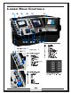
PrefaCe Lower HeLm ControLs 3837• U3 11/11 i
PrefaCe Using tHe owner's information Kit THE OWNER’S INFORMATION KIT CONTAINS: Qty. Item 1 Owner’s Guide (Varies) OEM information Please read the Owner’s Guide and OEM (Original Equipment Manufacturer) information carefully . Become familiar with the yacht, its components, and systems before attempting to operate . The Owner’s Information kit must be onboard when the yacht is in operation . If the yacht gets sold, the new owner must receive the Captains Kit .
PrefaCe OEM INFORMATION The OEM (Original Equipment Manufacturer) information is supplied by companies from whom Marquis Yachts has purchased components to install in your yacht . These components include, but are not limited to, standard items: • Engines • Sanitation System • Pumps and Batteries • Other additional Item The OEM information explains how to operate and maintain the components .
PrefaCe WarNiNg Marquis recoMMends that no persons be allowed to ride on the forward sunpad while the yacht is under power. sudden turning of the yacht or unseen wave surge can cause loss of balance resulting in injury or falling overboard.
MARQUIS YACHTS, L.L.C. OWNER REGISTRATION PO BOX 1010 PULASKI, WI 54162-1010 MARQUIS YACHTS, L.L.C.
tHIRD OWNeR ReGIStRAtION Owner's Name: ______________________________________________ Street Address: ______________________________________________ City: _____________________ State: _______ Zip Code: ____________ telephone: ( ___) __________________Date of Purchase: ___________ Purchased From: _____________________________________________ Boat Hull Identification Number: CDR ___________________________ third Owner Registration does not extend, alter, or transfer the marquis Limited Warranty.
YaChTing safeTY seCTion 1 YaCHting safetY YACHTING SAFETY IS YOUR RESPONSIBILITY . Fully understand the operating procedures and safety precautions outlined in the Owner’s Information Kit and this Owner’s Guide before operating the yacht . safe yachting is no accident . SAFE OPERATION SAFE OPERATION INCLUDES, BUT IS NOT LIMITED TO, THE FOLLOWING: • Keep the yacht and equipment in safe operating condition . Inspect the hull, engines, safety equipment, and all yachting gear regularly .
YaChTing safeTY seCTion 1 If a portable radio is onboard: • Keep the radio tuned to a station broadcasting frequent weather reports . Many yachting clubs fly weather signals; learn to recognize the following weather signals . WEATHER SIGNALS STORM PREPARATION Storms rarely appear without advance notice . If a storm is a possibility, keep a watch on the horizon, especially to the West, for the storm’s approach . Watch for changes in wind direction or cloud formations .
YaChTing safeTY • seCTion 1 Set anchor if there is doubt in continuing the cruise . Listen for other fog signals while continuing to sound the fog horn or bell . emergenCY ProCedUres It is important to obtain training to handle any emergency that may arise . The following is not an exhaustive list of situations that may be encountered while yachting; however, this section serves as a guide to aid in emergencies .
YaChTing safeTY seCTion 1 It is the owner and/or crew’s decision to abandon the yacht . If the decision is to abandon ship, all persons onboard should jump overboard, and swim to a safe distance away from the burning yacht . FLOODING If water is leaking in the hull, and the yacht is taking on water: 1 . Turn ON the bilge pumps . 2 . Assign someone to bail out the bilge and investigate the cause of the flooding . 3 . Attempt to repair the yacht when the source of the leak is found .
YaChTing safeTY seCTion 1 NEvEr never attach a tow line to a single deck cleat or anchor windlass. The cleats and windlass are not designed to take the full load of the yacht and may pull free from the deck, causing serious injury or property damage . MAN OVERbOARD In the event that someone falls overboard, understanding what to do is important . Emergency procedures are published in Chapman Piloting publications, and instruction is offered by the U .S . Coast Guard .
YaChTing safeTY seCTion 1 regulations to ensure that all the required safety equipment is onboard . It is the owner’s responsibility to learn about additional recommended equipment before operating their yacht . PERSONAL FLOTATION DEVICES (PFD’S) • • • A minimum of one personal flotation device is required for each person onboard . The PFD must be U .S . Coast Guard-approved wearable (Type I, II, or III) . The PFD’s must be readily accessible and in serviceable condition .
YaChTing safeTY seCTion 1 SOUND SIGNALING DEVICE The yacht must be equipped with an operable device that can produce a sound signal if conditions require . Required sound devices include: • One horn is standard on all Marquis models . • Yachts longer than 39’ 4”, one bell and one whistle is required . The devices must meet the Inland Navigational Rules Act of 1980 . For details on the appropriate signals, refer to the Navigational Rules published the U .S . Coast Guard, International-Inland .
YaChTing safeTY seCTion 1 The United States Inland Rules applies to all vessels inside the demarcation lines separating inland and international waters . The U .S . Coast Guard lists the traffic regulations in the Navigational Rules, International-Inland publication . A copy can be obtained from a local U .S . Coast Guard Unit or the United States Coast Guard Headquarters at: 1300 E . Street NW, Washington, D .C . 20226 . Other helpful publications available from the U .S .
YaChTing safeTY • • • seCTion 1 An injury requiring medical treatment beyond first aid Property damage in excess of $200 Complete loss of the vessel . In cases of death and injury, reports must be submitted within 48 hours . All other cases, reports must be submitted within 10 days . Reports must be submitted in the state where the accident occurred . YACHTING REGULATIONS It is the owner’s responsibility to make sure that the yacht is in compliance with all federal, state, and local regulations .
YaChTing safeTY seCTion 1 Carbon monoxide (Co) warnings CO detectors are standard on all Marquis yachts . Have the detectors professionally calibrated at regular intervals . DaNgEr r carbon MonoXide (co) is a colorless, odorless, and tasteless gas eMitted through engine and generator eXhaust. prolonged eXposure to co can result in unconsciousness, brain daMage, and death. carbon MonoXide (co) will cause serious injury or death. stay clear froM the eXhaust port when the engine is running.
YaChTing safeTY seCTion 1 Blockage of exhaust outlets can cause carbon monoxide to accumulate in the cabin and cockpit area; even when the hatches, windows, portholes, and doors are closed . warning: never operate the generator while the yacht is Moored against another yacht, dock, or wall structure that could block the eXhaust outlet. Exhaust from another vessel alongside your yacht, while docked or anchored, can emit poisonous CO gas inside the cabin and cockpit areas of your yacht .
YaChTing safeTY otHer HeaLtH seCTion 1 and safetY information WarNiNg g cancer, birth defects, and other reproductive harM are known by the state of california to be caused by cheMicals eMitted froM engine eXhaust, engine eXhaust constituents, and a variety of coMponents. cancer, birth defects, and other reproductive harM are known by the state of california to be caused by cheMicals contained or eMitted by oils, fuels, and fluids contained in yachts as well as waste produced by coMponent wear.
DC eleCTriCal sYsTem seCTion 2 dC eLeCtriCaL sYstem A 12-volt DC (Direct Current) electrical system is equipped on the 420 SC . The DC system is a comprehensive system designed to meet present and future 12-volt electrical needs . Wire-runs and connections are positioned to prevent abrasion and exposure to moisture, as well as to remain accessible for inspection, repairs, and the addition of aftermarket electrical accessories .
DC eleCTriCal sYsTem seCTion 2 NOTE: It is not necessary to start the engine to activate its voltmeter . Refer to the OEM information for details on operating the engines . Gauge Panel (Left) needs to be cycled to voltmeters and the engines at idle to indicate a correct running volt . ACCESSORY bATTERIES The voltage level of the accessory batteries is determined by using the voltmeter located on DC Control Panel (Salon) .
DC eleCTriCal sYsTem seCTion 2 While the batteries are relatively maintenance-free, a few things can be done to increase the batteries effectiveness and life . • Keep the batteries fully charged . Batteries that are kept fully or near fully charged last longer than batteries stored with a partial charge . The charge level of the batteries can be monitored using the voltmeters on the helm instrument panel (engine batteries) or tribulation panel (accessory batteries) .
DC eleCTriCal sYsTem seCTion 2 The DC Control Center (Engine Room, Starboard Bulkhead) manages the boat’s DC power systems located in the hull and lower level of the boat . The DC Control Center also controls the flow of electricity to the DC Control Panel (Salon) and various safety systems . Circuit Breakers SAFETY SYSTEM The safety systems include: • High water alarm .
DC eleCTriCal sYsTem seCTion 2 Refer to Section 1: Carbon Monoxide (CO) Warnings for more information on CO . STEREO MEMORY 1,2,3 High Water Alarm Sensor The stereo memory breakers control the stereo systems . The stereo memory breakers should always be ON to maintain the information programmed into the stereo’s memory . The stereos will need to be reprogrammed if the stereo memory breaker is switched OFF . Refer to the OEM information for details on programming the stereos .
DC eleCTriCal sYsTem seCTion 2 dC ControL PaneL (HeLm) The DC Control Panel (Salon), manages the power supply to the DC components listed on the panel . The panel is located in a cabinet in the starboard side of the helm . The DC Control Panel contains the circuit breakers described below . Each boat is different, and may not have every breaker described in this manual .
DC eleCTriCal sYsTem seCTion 2 The electronics circuit breaker controls the helm’s electronic equipment, i.e.: VHF radio and Navigational Electronics system. Refer to the OEM information for details on operatoperating the equipment.
DC eleCTriCal sYsTem seCTion 2 the lights fail to function . • If any breakers are tripped, repair the problem before resetting the breaker . • If no breakers are tripped, it may be a light has burned out . • For underwater lights, the problem may need to be addressed by qualified personnel . WATER MONITOR The water monitor breaker controls the fresh water monitoring system, including the water level gauge . Switch the breaker ON to supply power to the system .
DC eleCTriCal sYsTem seCTion 2 bATTERY SCHEMATIC 3837 • U3 11/2011 21
DC eleCTriCal sYsTem seCTion 2 DC SCHEMATIC 22 3837 • U3 11/2011
AC Electrical System Section 3 AC Electrical System A 50 amp AC (alternating current) electrical system is installed on the 420SC. The power for the system is supplied by either a shore power source or the onboard generator. The Shore Power Connection Procedure and the Onboard Generator Procedure are explained later in this section. • Shore 1 (120V/205V 60Hz) AC electrical system is designed for use in North America or the Pacific Rim.
aC eleCTriCal sYsTem seCTion 3 DaNgEr do not touch the black, red, or white wires while the ac electrical systeM is connected to a power source. each wire carries enough current to kill or cause serious injury. SHORE POWER Remove all perishables from the refrigerator if the boat is unoccupied for more than forty-eight hours . The shore power supply to the refrigerator may be interrupted and food may spoil .
aC eleCTriCal sYsTem Shore Water Connection seCTion 3 STEP 3: Unthread the access cap and lift cap up . Pay out cord as needed using the Cable Master Switch . Shore Power Cable Cable Master Switch STEP 4: Switch the External Cord and Cablemaster circuit breaker OFF, installed in the source box at the shore power station (Starboard Aft Locker Location) .
aC eleCTriCal sYsTem seCTion 3 regions . SWITCH THE SHORE CIRCUIT BREAKER GROUP off IF THE INDICATOR LIGHT ILLUMINATES . GERMANY OR ITALY 1 . 2 . 3 . 4 . Disconnect the shore power cord from the shore power source outlet Rotate the cord’s plug 180 degrees Plug the cord into the outlet again . Repeat connection procedure . If the Reverse Polarity indicator illuminates again, disconnect the shore power cord .
aC eleCTriCal sYsTem seCTion 3 STEP 3: Close the seacocks before removing the strainer; remove and clean the strainer . The strainer is located in the center of the engine room, bilge area between the Racor fuel filters . The generator engine uses a seawater cooling system . The cooling system includes a strainer that prevents debris in the seawater from entering the cooling system’s water pump . Seacock strainer detail Strainer STEP 4: Reinstall the strainer .
aC eleCTriCal sYsTem seCTion 3 STEP 11: Switch the Generator circuit breaker group off, located on the AC Control Center, to change the AC power source from the generator to shore power. Then connect to a shore power source as described earlier in this section . DaNgEr r do not inhale generator eXhaust. generator eXhaust contains carbon MonoXide, a poisonous gas. refer to the Carbon Monoxide Warnings portion of section 1 for More inforMation on engine eXhaust and carbon MonoXide.
AC Electrical System Section 3 not be fully explained, for example: Sauna circuit breaker (options) controls the team function in the shower/spa in the head. INDICATOR LIGHTS The indicator lights located on the front panel indicate that the generator is running or shore power is properly connected and available to the panel. The voltage display and ammeter display each read zero if the main breakers on the panel are OFF.
aC eleCTriCal sYsTem seCTion 3 DaNgEr strainer detail do not switch on the a/c systeM water puMp breaker until after the seacocks supplying the air conditioning systeM with seawaSeacock ter are opened. the puMp and seacocks are located in the engine Strainer rooM, forward of the starboard engine. groUnd faULt CirCUit interrUPters Each AC receptacle contains a Ground Fault Circuit Interrupter (GFCI) .
aC eleCTriCal sYsTem seCTion 3 bONDING SYSTEM A comprehensive metallic bonding system that interconnects all underwater equipment and thru-hull fittings is equipped on each model . The bonding system ensures that all metallic equipment onboard, including the fittings, have at the same electrical potential . The bonding system minimizes corrosion of the underwater fittings caused by stray electrical currents .
AC Electrical System Section 3 60Hz Electrical Schematic 3837 • U3 11/2011 32
internal system seCtiOn 4 air Conditioning sYstem Section 4 applies only, to the Interior Air Conditioning System installed at the Marquis Assembly Plant . NOTE: An aftermarket air conditioning system may not operate as the system explained in this section . The air conditioning system needs an AC power source to operate, supplied by: • Shore power or the generator • Supply of water (either salt or fresh) The factory-installed air conditioning system consists of three air conditioning units .
internal system POWERING THE AIR CONDITIONING 8 . 9 . seCtiOn 4 (CONTINUED) breaker must be ON while the air conditioning system is operating . Switch the Air Conditioning System Water Pump circuit breaker to ON, located on the AC Control Center (Salon) . Switch the desired Air Conditioning Unit circuit breakers ON . 10 . Verify that seawater is pumping through the air conditioning units . The seawater exits through the discharge thru-hull fittings on the side of the yacht . 11 .
internal system seCtiOn 4 freshwater systeM engineering scheMatic .
internal system seCtiOn 4 internal water systeM detail freshwater washdown pressure pump transom shower 36 3837 •U3 11/2011
internal system seCtiOn 4 PRESSURIZING AND PRIMING THE WATER SYSTEM Pressurize and prime the water system, ONLY after the fresh water tank is full . To pressurize and prime the water system: Pressure Relief Valve Shut Off Valves Drain 1 . 2 . 3 . 4 . 5 . 6 . 11 gallon tank - Shown (20 gallon similar) By Pass Valve Verify that the DC Control Panel (Helm) has power Switch ON the Auto Sump circuit breaker, located on the DC Control (Engine room) .
internal system seCtiOn 4 CauTiON do not supply power to the water heater when it is eMpty. daMage May occur to the heating eleMent. fill, pressurize, and priMe the fresh water systeM before turning on the water heater, as described in: Filling the Water tank and Pressurizing and PriMing the Water systeM.
internal system seCtiOn 4 tank and pressure water pump; water does not fill into the tank . The deck plate labeled WATER is the only way to fill the fresh water tank . Switch OFF the Pressure Water Pump circuit breaker, located on the DC Control Panel (Helm) when connecting to shore water . CauTiON do not leave the yacht unattended while connected to shore water. water May develop onboard if a water line leaks. CONNECTING TO SHORE WATER: 1 . 2 . 3 . 4 . 5 . 6 .
internal system seCtiOn 4 CauTiON never store iteMs in the bilges. storing loose iteMs in the bilges May daMage the puMps, pipes, or other coMponents essential for proper operation. the water in the bilges Must be drained before storing for the winter if the yacht is kept in a cliMate with below freezing teMperatures. frozen water in the bilges May cause severe daMage to the yacht and its coMponents. refer to section 8: bilges for More inforMation on winterizing the bilges.
internal system seCtiOn 4 NOTE: A light will illuminate on the manual switch at the helm when the bilge pumps are operating in either manual or automatic mode . The light indicates that the pumps are operating . A Tip From Marquis! A small amount of water always collects in your boat’s bilge. The water is usually not enough to activate the automatic switch on the bilge pump. While underway, use the helm switches to manually turn the bilge pumps on, and let the pumps run for 30 seconds to one minute.
internal system seCtiOn 4 GREY WATER SYSTEM Yachts equipped with a Grey Water System are designed to have the sinks and shower drain into the Sump, water drainage is pumped to the Grey Water tank . Once the grey water tank is full, the tank can be emptied at dock side with the procedure described on the next page, titled: Emptying The Waste/ Grey Water Tank . Before using the overboard discharge, make sure to be in a legal location .
internal system seCtiOn 4 the optimum level . NOTE: To eliminate the toilet vacuum pump noise, temporarily shut the pump off by using the Toilet switch . The switch is located on the Port Bulkhead . Placing the switch in the OFF position shuts off the toilet’s vacuum pump . waste plate (aft port location) EMPTYING THE WASTE TANK AND GREY WATER TANK dockside discharge Waste Tank Deck Plate TO EMPTY THE TANKS: Waste Tank Deck Key 1 . 2 . 3 . 4 . water plate (port location) 5 . 6 .
internal system seCtiOn 4 4 . Turn ON the Overboard Discharge Pump Switch . The switch is located near the overboard discharge seacock . The switch activates the overboard discharge pump, and pumps the waste overboard . CauTiON turn the overboard discharge puMp off when the waste tank is eMptied. the puMp can be daMaged by continuing operation when the waste tank is eMpty. waste plate (port aft location) Waste Tank Deck Plate Waste Tank Deck Key EMPTYING THE WASTE TANK (CONTINUED) 5 .
internal system seCtiOn 4 USING THE RAW WATER WASHDOWNS: Open 1 . Locate the bow and transom mounted hose fittings . Each location is as follows: • The bow-mounted fitting: located on the fore deck starboard of the anchor guide plate . • The transom-mounted fitting: located in the starboard aft access door for shore power/water . 2 . Attach one end of an appropriately sized nylon water hose (with nozzle) to the hose fitting of choice . Closed general seacock open/closed position 3 .
internal system seCtiOn 4 TRANSOM LEDGE/AFT bILGE AREA The valves located along the transom ledge in the bilge area are all to be placed in the OPEN position . The valve open position allows water to drain from the air conditioning units, water heater, aft bilge pump, and cockpit areas . Close the valves while the yacht is stored for the winter .
prOpulsiOn seCtiOn 5 ProPULsion The Volvo Penta IPS drive system is equipped on the 420 SC . Section 5 provides a general overview of the propulsion system and operation . For a detailed explanation of the engines, engine operation, and engine maintenance; refer to the OEM information provided with the boat . Diesel engines are standard on the Marquis Yacht .
prOpulsiOn seCtiOn 5 fuel systeM - diesel Open FUEL TRANSFER SYSTEM (CONTINUED) 3 . Closed general seacock detail determine when the fuel levels are equal . Turn OFF transfer pump and close the valves . NOTE: The fuel gauges are active when the ignition switches to the engines are ON . • Port engine = Port fuel gauge and Starboard • Engine = Starboard fuel gauge . The fuel transfer switch is a two position switch, and will transfer fuel from one tank to the other depending on the switch position .
prOpulsiOn seCtiOn 5 Make sure that a sufficient level of coolant mixture is kept in each system . open the cooling system seacocks before starting the engines. The inlet seacocks for each engine are located on the IPS drives . Clean the seawater strainer (located on the left front of the engine) every 14 days or sooner as necessary .
prOpulsiOn seCtiOn 5 FUEL SHUT-OFF VALVES Fuel supply shut-off valves are located on the top of the fuel tanks near the aft inboard corner . The valves must be open when operating the engines . FUEL TANK VENTS Open Closed general seacock detail Each fuel tank is vented overboard . During fueling, air is displaced from inside the tanks and the air escapes through the vents . However, when the engines are running, air enters the fuel tanks through the vents to displace the fuel being used .
prOpulsiOn Manual Override Display Monitor seCtiOn 5 WarNiNg iMMediately evacuate the engine rooM and the aft bilge area if the fire suppression systeM is activated. asphyXiation can result if the fire suppression systeM cheMicals are inhaled. iMMediately ventilate the engine rooM with fresh air once the fire is eXtinguished and the systeM is deactivated.
prOpulsiOn seCtiOn 5 SHIFT-THROTTLE LEVERS Two shift-throttle levers allows the operative to shift the engines from, neutral to forward or neutral to reverse, to control the engines’ RPM’s . See below for lever position guide: 1. above neutral position: Shifts the engines to forward and increases the RPM levels 2. center position: The engines remain in neutral at their lowest RPM levels . 3.
prOpulsiOn seCtiOn 5 neutral position and the engines are running . Refer to the Owner’s Manual for complete information on the controller’s features . CauTiON the joystick and joystick functions are only to be used while docking. the wheel and control levers are to be used for all other functions.
prOpulsiOn MAIN Circuit Breaker seCtiOn 5 Pre-start CHeCKList 1 . 2 . 3 . Read and understand the Owner’s Guide and all OEM information . Check both fuel gauges to verify that the yacht is sufficiently fueled for the trip . Inspect the engine room: 3a . Check fuel system for any signs of leakage . 3b . Check the bilge water level . 3c . Check for oil in the bilge . 3d . Check the crank case oil level in each engine . 3e . Make an overall inspection of the engine room for signs of potential problems .
prOpulsiOn seCtiOn 5 10 seconds, release the ignition key, and try starting the engine again. 4 . 5 . Turn the ignition switch clockwise to the start position . The engine should crank and start within 10 seconds . Start the next engine, same as the first when the first engine is idling smoothly . ONCE THE ENGINES HAVE STARTED 1 . Check the engine gauges . Verify that all readings on the helm are within the normal range . 2 .
prOpulsiOn seCtiOn 5 PagE iNTENTiONaLLY LEFT BLaNK 56 3837 • U3 11/2011
OperatinG and maneuverinG seCtiOn 6 LaUnCHing tHe YaCHt Have a professional launch the yacht . Your dealer can either provide experienced people or recommend someone to launch . navigation Understanding navigation is very important when out on the open seas . Instructions on navigation are beyond the scope of this guide . Reading Chapman’s Piloting and Seamanship, to obtain instruction regarding navigation is encouraged by Marquis .
OperatinG and maneuverinG seCtiOn 6 yacht . CASTING OFF AND DOCKING Docking and casting off can be hampered by wind and current . It is important to use the current by approaching or leaving with the current instead of fighting against it . Also, the operator should adequately fender the yacht against collisions with docks or other boats . If a dinghy is used to reach the yacht, make sure the dinghy line does not foul the propeller .
OperatinG and maneuverinG seCtiOn 6 Stopping the yacht’s forward motion is referred to as “checking headway” . It is important learn how to confidently stop the yacht within any required distance . Check headway by shifting engines to neutral and coming to a complete stop over a long distance, or by reversing engines and stopping within a shorter distance . TOWING ALWAYS OFFER ASSISTANCE TO A VESSEL IN DISTRESS . However, towing a capsized yacht or a yacht with a damaged hull is not recommended .
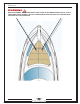
OperatinG and maneuverinG seCtiOn 6 MOORING LINES Become familiarized with mooring line terminology and mooring line use . Obtain training on mooring if necessary . Learn how and when to tie the various knots used in seamanship . Yachts that are not moored correctly can suffer and cause serious damage . The following information serves only as a guide to mooring the yacht . The mooring illustration on the previous page demonstrates possible mooring lines for a small vessel .
OperatinG and maneuverinG seCtiOn 6 OPERATING AT PLANING SPEED The yacht is equipped a “planing” hull . A planing hull skims over the water rather than through it . Planing is performed by first reaching a certain speed, called planing speed . The trim angle of the yacht increases, when accelerating from a dead stop, causing the bow to rise and the stern to drop . The yacht eventually achieves plane, if acceleration continues, which means the bow slowly drops to a more level attitude .
OperatinG and maneuverinG seCtiOn 6 PagE iNTENTiONaLLY LEFT BLaNK 62 3837 • U3 11/2011
maintenanCe seCtiOn 7 maintenanCe sCHedULe The maintenance activities and the intervals listed on the following pages are provided as guidelines only . The ideal maintenance activities and maintenance schedule depend on the components installed on the yacht, and the manner and environment in which the yacht is used . The more frequently the yacht is used, the more maintenance that needs to be performed . If the yacht is used in salt water, more maintenance is required, especially on the exterior .
maintenanCe seCtiOn 7 STEERING SYSTEM Inspect linkage and connections . Inspect fluid levels . Inspect seals .
maintenanCe seCtiOn 7 exterior maintenanCe The Exterior Maintenance section explains how to maintain various materials located on the cabin exterior, and how to help keep the yacht looking new . FIbERGLASS SURFACES The exterior fiberglass surfaces are coated with a protective layer of gelcoat . Gelcoat forms a hard, smooth and durable surface . Gelcoat contains microscopic pores that, over time, can collect dirt and discolor if the gelcoat is not kept clean .
maintenanCe seCtiOn 7 A gelcoat repair kit is available from your Marquis Dealer (Marquis part number 82036-03) . The kit includes: color matched gel, gel hardener, and detailed instructions on making gelcoat repairs . GELCOAT bLISTERS Fiberglass is a durable and economical material, however; it is not indestructible . Blistering is the most problem associated with fiberglass . The blisters generally form in the gelcoat or in the outer most layer of laminate .
maintenanCe seCtiOn 7 cleaning . If rust appears on the metal, remove it immediately with 3M Metal Restorer (Marquis part number 051131) . Failure remove rust leads to irreversible pitting . Use brass, silver, or chrome polish to remove rust on stainless steel . Wax the stainless fittings and rails to help protect both surfaces from the elements and keep them looking their best . Use the same wax on the fiberglass surfaces of the yacht .
maintenanCe seCtiOn 7 for details on cleaning the Sunbrella fabric . CauTiON fabric Must be coMpletely dry before storage. Moisture on stored fabric can cause the glass to cloud, and the fabric and thread to break down. PREP THE FABRIC FOR STORAGE: 1 . Thoroughly air dry the fabric . 2 . If possible, store the fabric in a flat position (avoid rolling the fabric) . 3 . Avoid storing the fabric with the zipper(s) exposed to eliminate imprints into the next curtain . 4 .
maintenanCe seCtiOn 7 FILLING DENTS IN WOOD FINISH 1 . 2 . 3 . 4 . 5 . 6 . 7 . Locate the correct Burn Sticks color to match finished wood . Apply Burn in Balm around area of patch to protect wood from heat . Melt material into dented or chipped area . Level the patched area with an iron and remove any excess Burn Stick material . Scuff area with 600 grit sandpaper . Apply Poly Sealer TH-20 over affected area: 3 to 4 coats with a paintbrush .
maintenanCe 8103211 8103212 8697610 8697229 8697188 seCtiOn 7 Toner Catalyst TH-720 Topcoat Catalyst TH-2537 400 Grit Sanding Disk 600 Grit Sanding Disk 800 Grit Sanding Disk MATERIAL LIST (CONTINUED) PART NUMbER MATERIAL 8697618 8601218 8697496 ------8601207 8619411 ------- 1200 Grit Sanding Disk 1500 Grit Sanding Disk 15 Micron Polishing Disk Burn in Balm from Mohawk Burn Sticks from Mohawk 3M Extra Cut Compound (1st Buff) 3M Finesse It Final Finish Compound (Final Buff) 3M Perfect It Buffing Pad #
maintenanCe seCtiOn 7 The interior carpet has been treated with a stain protector; however, the carpet still needs periodic cleaning . Care for the carpet in the yacht the same as carpeting is cared for at home . Vacuum often, and shampoo as needed using carpet shampoo . New carpet sheds, and needs to be vacuumed frequently . Shedding is normal, and will stop after a few weeks .
maintenanCe seCtiOn 7 DaNgEr r wear gloves when handling a propeller. the propeller blades are very sharp. A Tip From Marquis! Consider purchasing and carrying a spare set of props onboard. Many marine dealers do not carry a full inventory of replacement propellers . A spare set allows your vacation or cruise to continue in the event that the primary set of props are damaged. DC ELECTRICAL SYSTEM Poor battery maintenance causes the majority of difficulties with the 12-volt DC electrical system .
maintenanCe seCtiOn 7 cause the pressure water pump to repeatedly cycle on and off . SUMP Clean the sump and sump filter frequently . Hair, dirt, and soap scum collects in the sump, and if not removed, eventually clog the sump pump or sump hoses . bILGE SYSTEM Keeping the bilges clean is important . A dirty bilge leads to clogged bilge pumps and unpleasant odors in the cabin . Keeping the bilges dry helps reduce moisture in the cabin .
maintenanCe seCtiOn 7 PagE iNTENTiONaLLY LEFT BLaNK 74 3837 • U3 11/2011
winterizatiOn and stOraGe seCtiOn 8 winterization: storage The yacht must be properly “winterized” before storing for an extended period of time, while temperatures could fall below freezing . Winterizing the yacht removes all water from its various systems . Water left on board could cause extensive damage to the yacht and internal systems . Marquis Yachts recommends hiring a professional to perform the winterization of yacht .
winterizatiOn and stOraGe seCtiOn 8 CauTiON reMove the internal battery to prevent freeze daMage if the boat is not stored in a heated facility. refer to the oeM inforMation for reMoval procedures. AIR CONDITIONING SYSTEM Refer to the OEM information for details on winterizing the air conditioning system . Marquis Yachts winterizes the air condition system in-house . FRESH WATER SYSTEM Refer to Section 4: Fresh Water System for a description of the boat’s fresh water system .
winterizatiOn 2 . 3 . 4 . and stOraGe seCtiOn 8 Close all faucets . Switch ON the Pressure Water Pump circuit breaker . If the optional grey water holding system is not supplied on the boat, place a large bucket under the grey water and sump discharge fittings . The bucket catches the antifreeze pumped out described in STEP 5 . Refer to Section 9: Thru-Hull Fittings for the exact location of the fitting . TRANSOM HAND SHOWER, bOW AND TRANSOM FRESH WATER WASHDOWNS ONLY: 4a .
winterizatiOn and stOraGe seCtiOn 8 Refer to Section 4: Bilge System, for a description of the bilge system . bILGE DRAINAGE PROCEDURE: 1 . 2 . 3 . Open the hull drain . Leave the drain open while the boat is in storage . Remove all water from the bilge . Clean the bilge as described in Section 7: Bilge System . SANITATION SYSTEM Pull the yacht from the water before performing the Standard Sanitation System procedure .
winterizatiOn and stOraGe seCtiOn 8 GREY WATER HOLDING SYSTEM Before performing the optional grey water holding system procedure, the boat should be pulled from the water . Winterize the grey water holding system only after the fresh water system has been winterized . There are two types of grey water holding systems: the standard system and the overboard discharge system . STANDARD GREY WATER TANK SYSTEM 1 . 2 . Empty the grey water tank as described in Section 4: Grey Water Holding System .
winterizatiOn • • • • • and stOraGe seCtiOn 8 Check the zinc sacrificial anodes for deterioration . Have the zincs replaced before spring launch if signs of deterioration show Check stainless steel rails and fittings for signs of rust . Remove rust prior to winter lay-up . Inspect the underwater portions of the hull . Review anything that looks out of the ordinary with your Marquis Dealer .
winterizatiOn and stOraGe seCtiOn 8 sPring reCommissioning CHeCKList Before launching for the first time of the season, complete the following checklist .
winterizatiOn and stOraGe seCtiOn 8 PagE iNTENTiONaLLY LEFT BLaNK 82 3837 • U3 11/2011
warranty and parts seCtiOn 9 warrantY information Marquis Yachts warrants every boat we manufacture, explained in the Marquis Limited Warranty . A copy of the warranty is located at the end of this section . Please review the warranty carefully . To ensure that the warranty remains in effect during its lifetime, Marquis Yachts, your Marquis Dealer, and you (the owner) all must uphold specific responsibilities . Marquis’s responsibilities are described in the Marquis Limited Warranty .
warranty and parts seCtiOn 9 obtaining warrantY serviCe The following requirements must be met before warranty work can be performed on the yacht . 1 . Registration of the yacht with Marquis Yachts is required . Register by completing, and submitting the Pre-Delivery Service Record to Marquis Yachts, P .O . Box 1010, Pulaski, WI 54162-1010 . 2 . Pre-Delivery Service must be completed by your Marquis Dealer . Information about the Pre-Delivery Service can be found in the preface of this manual .
warranty and parts seCtiOn 9 Bridge Clearance (waterline to arch) . . . . . . . . . . . . . . . . . . . . . . . . . . . . . . . . . . . . . . . . 14’0” (4 .2 m) Cabin Headroom . . . . . . . . . . . . . . . . . . . . . . . . . . . . . . . . . . . . . . . . . . . . . . . . . . . . . . . . . 6'5" (2 m) Draft . . . . . . . . . . . . . . . . . . . . . . . . . . . . . . . . . . .
warranty biLL 86 and of parts seCtiOn 9 materiaLs 3837 • U3 11/2011
warranty and parts seCtiOn 9 marqUis Limited warrantY 3837 • U3 11/2011 87
warranty and parts seCtiOn 9 PagE iNTENTiONaLLY LEFT BLaNK 88 3837 • U3 11/2011
OptiOns PassereLLe The extendable gangplank is hidden under the decking at the Starboard entrance gate . The system is a battery operated, hydraulic mechanism . The controls are mounted on the bulkhead in the aft port side of the boat . The hydraulic unit located is in the engine room (Starboard side aft of the water heater) . Circuit breaker is on DC Control Center (Engine Room) .
OptiOns eLeCtroniCs PaCKage The boat can be equipped with various electronic options from Raymarine . A fully equipped helm is shown on the image below . The power for the controls is supplied by the DC buss, accessory battery system (refer to Section 2: DC Electrical System for complete information) . Make sure the main DC disconnect switch is ON and supplying power to DC Panel (Helm) . The circuit breakers for the bridge electronics are located under the dash below the steering wheel .
OptiOns signed used to lift people. all persons Must be clear while raising and lowering the platforM due to the pinch point where the platforM Meets the hull. platform control hydraulic swim platform hydraulic pump (engine rm.