
PVKIT 2.0 Installation Instructions

The Right Way
TM
to attach almost anything to metal roofs!
888-825-3432 www.S-5.com
PV Kit 2.0 Installation Instructions
Installation Instructions
S-5!® Warning! Please use these products responsibly! Visit our website or contact your S-5! distributor for available load test results. The
user and/or the installer of these parts is responsible for all necessary engineering and design for the intended use of these parts in an
assembly or application. Note that a continuous ground must be followed in accordance with National Electric Code (NEC), ANSI/NFPA 70.
Installation in Canada must be in accordance with CSA C22.1, Safety Standard for Electrical Installations, Canadian Electrical Code, Part 1. For
UL 2703 Listed assemblies (UL Listed) use with PV Modules having a maximum fuse rating of 25A or less. Prior to installation, contact the
local code Authority Having Jurisdiction (AHJ) to determine the proper grounding requirements. Visit www.S-5.com for more details.
Exercise care when threading the Male Portion of the StandO into the clamp to avoid cross-threading.
Tools Needed
• Screw Gun
• T-30 Torx Bit Tip
(provided)
• Calibrated Dial
Torque Wrench
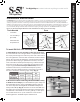
1. Install the rst row of S-5! clamps, at the edge of the array:
It is critical that this row is straight. Install a clamp at both ends of
the row, by measuring from a reference point such as the eave of
the roof. Tighten the setscrews with Screw Gun and the included
Bit Tip. The setscrews will dimple the seam material but will not
penetrate it. When relying on published load values, setscrew
tension should be verified periodically using a calibrated torque
wrench to ensure the tool is consistently achieving the proper
torque range (see Setscr
ew Torque Table below). Please see
installation instructions provided with clamps for specics.
Stretch a string line between the two end clamps to provide a
true line to mount the remaining edge clamps (Fig. 1).
To install PV Kit 2.0 On Standing Seam
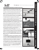
Parts
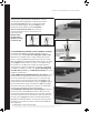
2. Mount the PV Disks and the EdgeGrab/StandO
Assembly
to the rst row of clamps: place the PV Disk atop the clamp and
thread the Male Portion of the StandO through the disk and
into the clamp. Drive the EdgeGrab/StandOff Assembly down
with provided Bit Tip (Fig. 2) until the base of the StandO seats
the disk in place and breaks the thread locking seal between the
StandOff and Low Profile Bolt. Leave the grab up, to allow space
for a module frame. A 1/2” open end wrench can be used to
further tighten the StandOff atop the disk if desired.
PV Disk
StandO
EdgeGrab/StandO Assembly
MidGrab/StandO Assem
bly
Wire Management
Tie O Holes
Module Placement
Bevel Guide
Bonding Teeth
Male Portion
cutaway for 1/2”
wrench option
EdgeGrab
Low Prole
Bolt
Accessory
Slot
T-30 Torx
Drive
T-30 Torx
Drive
Thread locking
compound
1.
2.
MidGrab
StandO
Low Prole
Bolt
S-5! Clamp Setscrew Torque Table (torque varies depending on roof material)