
Installation Guide

To Install CorruBracket™ 100T or CorruBracket™ 100T Mini
B) Attaching to supporting structure
CorruBracket™ 100T and CorruBracket™ 100T Mini
Installation Instructions
S-5!® Warning! Please use this product responsibly!
Products are protected by multiple U.S. and foreign patents. For published data regarding holding strength, fastener torque, patents, and trademarks, visit the S-5! website at www.S-5.com.
Copyright 2015, Metal Roof Innovations, Ltd. S-5! products are patent protected.
S-5! aggressively protects its patents, trademarks, and copyrights. Version 011515.
1
2
3
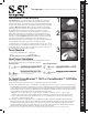
CorruBracket™ 100T Placement Tips
a
a) Horizontal bracket alignment
To ensure brackets are installed in a straight line when desired,
install a single CorruBracket
TM
100T on each end of the roof at a
measured, consistent distance from the bottom edge of the roof. Use a
string line between the two brackets. Mount the remaining CorruBracket
TM
100T along the string line, directly into the roof.
b) Upslope bracket spacing
For upslope bracket spacing techniques reference the S-5! website at
www.S-5.com
.
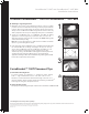
1. Determine the location of the supporting structure of the roof. When
possible secure the CorruBracket™ 100T using all of the pre-punched hole
locations; when not possible, always use the two upslope hole locations.
Always secure CorruBracket 100T Mini using both hole locations. The only
surface preparation necessary is to simply wipe away excess oil and debris.
2.
Secure the CorruBracket 100T or CorruBracket 100T Mini by driving
appropriate screws through the pre-punched holes and into the
supporting structure of the roof. Do not remove the EPDM rubber gasket
as this is for weather-proofing.
Note: Do not over-drive fasteners; a slight extrusion of rubber around the
washer is a good visual-tightness check.
3. From either end of the CorruBracket 100T or CorruBracket 100T Mini, slide
the included M8-1.25 hex flange nut (flange side up) into the top
groove. The CorruBracket 100T and CorruBracket 100T Mini are now
ready to install the S-5-PV Kit by insertion of the PV stud, or other
ancillaries by using a standard M8 bolt
through the slotted top thru-hole
and the previously inserted hex flange nut. For critical attachment
applications utilizing an M8-1.25 X 16 mm He
x Flange Bolt, tighten the M8
bolt to 160 inch pounds (13 foot pounds).
CB100TI-V1.0-0915