
Install Manual


GRIPPERFIX™ Installation Instructions
S-5!® Warning! Please use this product responsibly!
Products are protected by multiple U.S. and foreign patents. For published data regarding holding strength, fastener torque, patents, and trademarks, visit the S-5! website at www. S-5.com.
Copyright 2018, Metal Roof Innovations, Ltd. S-5! products are patent protected. S-5! aggressively protects its patents, trademarks, and copyrights.
3.
4.
5.
6.
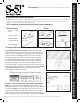
3. Attach the
GRIPPERFIX Rail to the clamps: Align the two S-5-
Tab CF that were inserted into the rail in step 2, such that they set
atop the clamps, and the GRIPPERFIX Rail rests on the ribs of the
roof (Fig. 3). The rail should be centered left to right with equal
cantilever. Using 16 mm M8-1.25 Hex ange bolts (provided with
clamps), attach the tabs to the clamps. Bolts should be threaded
into clamp but left loose at this point to allow for adjustability.
4. Installing the remaining two clamps and
GRIPPERFIX
Rail: Measure the center to center distance between upslope
and downslope mounting points on the condenser units feet.
Install the second row of clamps on the roof following the
same procedure from step 1, so that the bolt slots atop the two
GRIPPERFIX Rails are the same distance (from eave to ridge) apart
as the distance between the condenser unit’s mounting points
when mounted to the clamps. Place the two GRIPPERFIX rails
on the clamps with both S-5-Tab CF resting atop the clamps.
Each GRIPPERFIX Rail should be on the side of the clamp that is
nearest the opposing set of clamps (Fig. 4). Using M8-1.25 x 16
mm Hex ange bolts (provided with clamps), attach the tabs
to the clamps. The Slotted Holes on the S-5-Tab CF allow for
adjustability should clamp placement be slightly o. Bolts should
be threaded into clamp but left loose at this point to allow for
adjustment later, when placing the condenser unit.
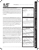
5. Slide M8-1.25 x 40 mm Bolts into Bolt Slot and place
Damper Pads: Slide (2) M8-1.25 x 40 mm bolts into the top slot
of each
GRIPPERFIX Rail (Fig. 5). Measure the center to center
horizontal distance between mounting holes on the condenser
unit’s feet. Position M8-1.25 x 40 mm bolts such that they align
with mounting holes of the condenser unit centered on the
GRIPPERFIX Rail. Place Damper Pads over the shafts of the inserted
bolts.
6. Place condenser unit mounting holes over M8-1.25 x 40
mm Bolts atop Damper Pads and Fix to
GRIPPERFIX Rail: Some
adjustment of the M8-1.25 x 40 mm Bolts & Damper Pads may
be necessary to align with mounting holes of condenser unit.
Additional Damper Pads can be added to the downslope
mounting locations to level the condenser unit if necessary.
Place the mounting holes on the feet of the condenser unit over
the M8-1.25 x 40 mm bolts. Thread the M8-1.25 Nuts onto the
M8-1.25 x 40 mm Bolts. Nuts should be torqued to 18 Nm (160
in lbs). Bolts atop clamps that were left loose in steps 3-4 should
now be torqued to 18 Nm (160 in lbs). (Fig. 6)
4.